Leaderboard


Popular Content
Showing content with the highest reputation since 07/18/2024 in all areas
-
I have now updated the following scripts for FS25 (zip file containing all scripts listed available at the bottom of this post) To avoid confusion all future Updates to any of the scripts will require the complete FS 25 Script Versions.zip to be downloaded Fence Power Placement --Updated 07/01/2025 Stay Upright Option removed fence/poles now automatically placed upright --15/06/25 Problem with upright position and placement when spline has a tight curve solved. Paint Foliage by Spline Panel Spline CSV Creator Panel - Updated 15/06/25 see changelog below Spline Height Panel Spline Paint Panel --- Updated 20/01/2025 Random value problem fixed and UI Changes -- see note in Spline Paint Panel below Spline Placement Panel Combined --Updated 02/01/2025 Interim fix to first object placement problem --15/06/2025 Rotation/Placement problem fixed Fence Power Placement Fence Power Placement Script updated to cure problem with pole's not remaining upright and pole placement not following spline correctly when spline has a tight curve, refer to tutorial for operation Tutorial https://farmerboysmodding.com/index.php?/topic/2452-fence-power-placement-script/ Spline CSV Creator Panel Spline CSV Creator Panel OBJ_25 ChangeLog Script operation is the same output has changed slightly A new CSVSpline transform group is automatically created in the Scenegraph and the new CSV spline is created in this TG. The new CSV spline ,spline.obj and csvData.txt are still added to the CSVData folder in the maps folder (same place as the map.i3d )which now has Paint Foliage by Spline Panel Operation of the script is still the same but the Panel Layout has changed. Note: Random Foliage Paint will paint all states of a selected foliage. Variable Foliage state When selected along with Random Foliage Paint option allows only the states entered in Set Foliage State and Set Second Foliage State to be painted. Random Foliage Distance seed can be adjusted by changing the Set Distance Between Foliage value Spline Height Panel Script just updated refer to tutorial for operation Spline Paint Panel Script just updated refer to tutorial for operation For further information on the above scripts refer to the tutorial https://farmerboysmodding.com/index.php?/topic/2439-new-spline-paint-height-csv-field-creationdimension-panel-scripts/ Note: Random Width (Max) this is the max distance the texture will be painted either side of the spline (0 to Random Width (Max)) Random Distance (Max) this value is used by the RND function for the random distance the texture will be painted along the spline (0 to Random Distance (Max)) In both cases texture will be painted randomly at a distance between 0 and Random value entered at each point along the spline Random distance bewteen textures can also be adjusted using the Set Texture Distance Value Spline Placement Panel Combined Script update with some Panel Layout changes and addition Unfortunately the Use Distance Table values still have to be entered in the User Attributes panel. (now in seperate tab in the Attributes Panel) I hope to combine them into the main panel at a later date. Addition Fixed Distance -- is the distance away from the spline (both + and -) you want the placement to start (Look at it like a duplicate spline at the Fixed Distance value) Changes Select Random Spline Order – now uses the number of objects in the objectsTo Place TG as a random seed If only one item in the objectsToPlace TG then I suggest adding a empty TG to the objectsToPlace TG before selecting Select Random Placement -- is the max distance around the spline (inc any Fixed Distance values) Select Random Distance -- uses the Object Distance as seed to generate the random distance If Use Distance Table Selected then Select Random Spline Order and Select Random Distance is disabled. See the tutorial for further information. https://farmerboysmodding.com/index.php?/topic/2469-spline-placement-combined-panel/ There seems to be some confusion on where these scripts should be placed they should be placed here C:/Users/*****/AppData/Local\GIANTS Editor 64bit 10.0.3/scripts -- replace ***** with your computers user name not in the C:/Program Files/GIANTS Sosftware/GIANTS_Editor_10.0.3 folder as the scripts in this folder will be overwritten/updated when a new version is available. To avoid confusion all future Updates to any of the scripts will require the complete FS 25 Script Versions.zip to be downloaded and unzipped replacing any existing scripts in the GE scripts folder. FS25 Script Versions Updated.zip13 points
-
Version 31.01.25.01
519 downloads
Update Version 31.01.25.01 Fixed AI back node per MP7REEPER Update Version 03.01.25.02 Worked on work areas to try and eliminate the left-over material issues. Update Version 03.01.25.01 Fixed covers Credit to Deaf Gamer for letting me know of the issue. Update Version 30.12.24.02 Fixed more lights again Update Version 30.12.24.01 Fixed more lights, added a couple parts to arms. Update Version 29.12.24.02 Thanks for finding the issue SPUDS. Sorry fixed mass issues, will pull normal when loaded, will not try to break your tractor. Update Version 29.12.24.01 Added visual hoses Update Version 28.12.24.01 Big update: added a Stone Picker version found in the stone picker category in shop Fixed 1 million fill unit capacity. Still having issues with giants linked lights, "hope" this is fixed. Update Version 25.12.24.02 Sorry for all the updates. Realized I missed a giants lighting issue, I was also able to get hired worker to work, not noted in last update the pickup can be lowered/raised regardless of folding state. Update Version 25.12.24.01 Huge thank you to everyone who has helped find some issues. Please feel free to give feedback so I can get issues fixed. Alpaca78Billy informed me that wheels247 was having issues with pickup and color was reverting back to default color from distance. Color is now fixed. I could not replicate the pickup issue however I did adjust max pickup to possibly address this issue. Barry J informed me Bundy found that I forgot to add multiplayer support, this was fixed in update. JUMBO 8450 DB WR Forage wagon with windrowing arms. Cost 125000 Option to remove collision of arms. Capacity 50K - Free 100K – 2000 500K – 10000 1M – 50000 Discharge options free (when matched up correctly the unit will empty in around 10 seconds) 5K LPS 10K LPS 50K LPS 100K LPS4 points -
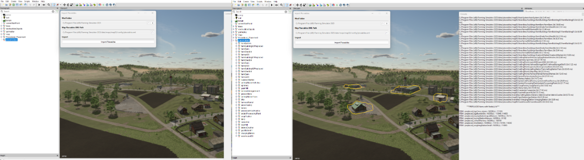
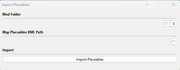
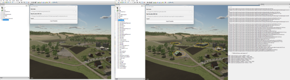
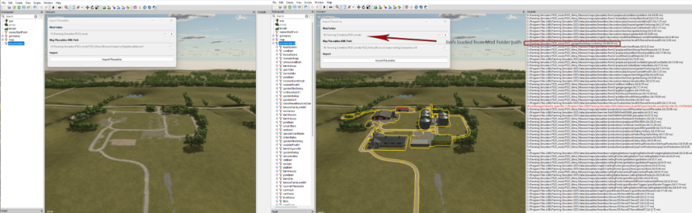
FS25 Import Placeables This is an updated version of the FS22 script which allowed the import into a map of all the placeable items in the placeables.xml (placeables.xml can be from a save game or another map) Original available here https://farmerboysmodding.com/index.php?/topic/2480-import-placeables/ With the changes made to placeables in FS25 the script will only import placeables that are not already in the map i.e. those who have not been preplaced using the placeables.xml <placeable isPreplaced="true" , any subsequent changes made to position/user attribute etc will still have to entered manually in the placeables.xml or by the Placeables Toolkit. However it will list all preplaced items in alphabetical order with their corresponding nodeId's for reference after the filepaths of the non preplaced items are printed in the console log. There are no requirements for setting any filepaths using the Script Editor. Installation and Use To use the script unzip the FS25_Import_Placeables.zip (available at the end of this tutorial) and copy/paste the folder to the location of your GIANTS Editor 64bit 10.0.4/scripts folder in this case it is, C:/Users/*****/AppData/Local/GIANTS Editor 64bit 10.0.4/scripts (replacing the *** with your computer name) Open GE and Select -- Scripts --FS25 Import Placeables When the script is first executed a check will be made to see if a 'placeholders' TG already exisits and if there is one or more instances of 'placeholders' TG's then a Warning will appear in the log with the duplicate 'placeholders' TG nodes for reference and investigation (if needed). A new placeholders TG will also have been created in the Scenegraph complete with the correct User Attributes (Placeholders.onCreate) With the Placeholders.onCreate added it will allow the placables to be seen in GE, the new placeable imports will be ignored when the map is opened in game and the placeables/preplaceables will be loaded as normal from the placeables.xml The script treats the preplaced placeables and normal placeables (those not preplaced and with a filename) in different ways. Normal placeables are loaded into placeholders TG in the Scenegraph and a print out of the file path to each one loaded will appear in the GE Console log. The name of each individual placeable in the Scenegraph will be its xml/i3d name not its placeable folder name. Preplaced placeables (if listed in the placeables.xml) are listed in the console log in alphabetical order together with their name and node Id's for reference (after the normal placeables filepaths). The following popup panel will also appear. Mod Folder Select the folder icon at the end of the Mod Folder line a file browser will appear navigate to where the folder containing any mods required by the map. For example if the map uses any external mods ( Required Mods ) in the normal My Games folder then the path would be :- C:/Users/****/Documents/My Games/FarmingSimulator2025/mods (obviously *** would be replaced by your computers name) Or if the mods folder is located elsewhere then something like this D:/Farming Simulator/FS25_mods Or if just importing from a map with no Required Mods D:/Farming Simulator/FS25_mods/FS25_SuperMap Basically the Mod Folder is the map/mods path where the placeables to be imported into the map are located. Note: All mods/maps must be unzipped for this to work correctly. Map Placeables XML Path Opening the file browser as before (selecting the relevant folder Icon) navigate to where the maps placeables.xml is located and select it. With the placeholders TG selected in the Scenegraph, select the Import Placeables button (move mouse away from the popup panel and wait for the Import Placeables button to turn back to white). The placeables will have been imported into the map at their relevant positions and a print out will appear in the consol log detailing the placeables file paths and also any preplaced placeables with their corresponding nodeId’s for reference. Some examples below the first using the default EU map (Zielonka) and the second using the Alma Missouri map EU map (Zielonka) Alma Missouri Limitations: Where fences/hedges/power lines have been created using the in game construction tool and then copy pasted into the placeables.xml from a save game these will not appear in their assigned position as any editing/deletion must be carried out in game and the placeables.xml manually adjusted from a new save game. The script relies on the placeables.xml being created correctly either by the Placeholders Toolkit or manually using the correct FS25 format (preplaced items must be created using the Placeables Toolkit to get the correct uniqueId) Script will only import placeables from i3ds so any placeables.xml script that does not have an i3dPath in its base.filename will not be loaded and an error message with the problem xml's filePath will be printed in the console log error message will also be printed if the mod directory doesn't have a mod associated with that map. The script will continue running until all placeables/preplaced types listed (including error messages) in the placeables.xml have been loaded It is possible to import all the placeables from one map into another (or even from a savegame) by opening the map in GE that is to receive the placeables and setting the Mod Folder to the donor maps filepath and Map Placeables XML Path to the donor maps placeables.xml then with the placeholders TG selected, select Import Placeables, placeables will be imported into the new map at their original positions. Placeables filepaths will still refer to the original map so adjustment will be needed if items kept. FS25 Import Placeables.zip
 3 points
 -
Version 31.01.25.01
240 downloads
Update Version 31.01.25.01 Fixed AI back node per MP7REEPER Update Version 04.01.25.02 Thank you BigDaddy for letting me know about the texture errors. Fixed \Windrowing Balers Windrowers added to: John Deere C441R (round wrapper) & Kuhn 1290 (square) Wrapper version has been adjusted to allow continuous baling. Tractor will be slowed down to allow time for wrapping and bale drop to occur. Wrapping has been drastically sped up. Cost 80000 Option to remove collision of arms. 2 Design color Rim color Hub color Silage additive standard Doubled consumables capacity3 points -
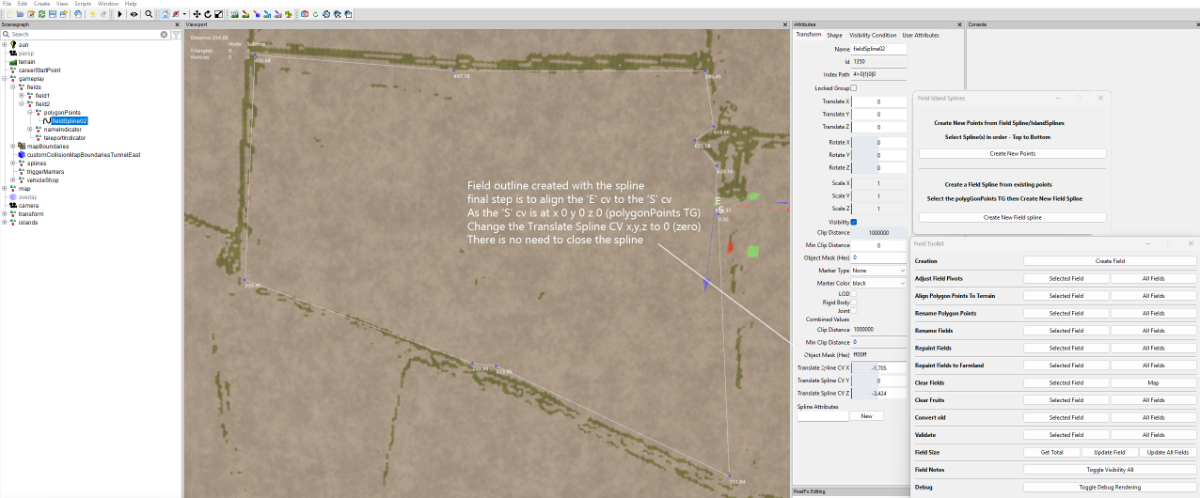
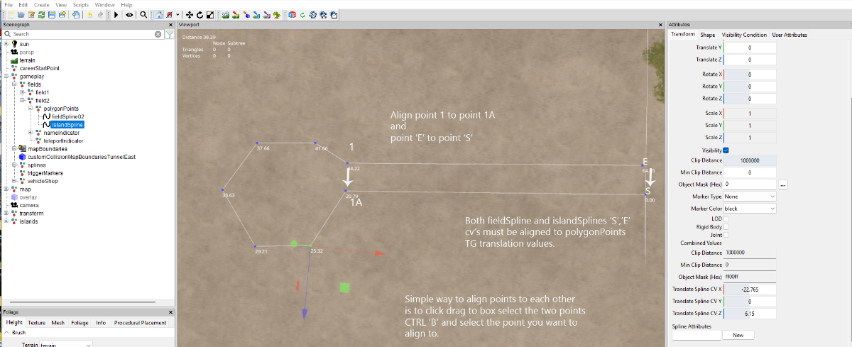
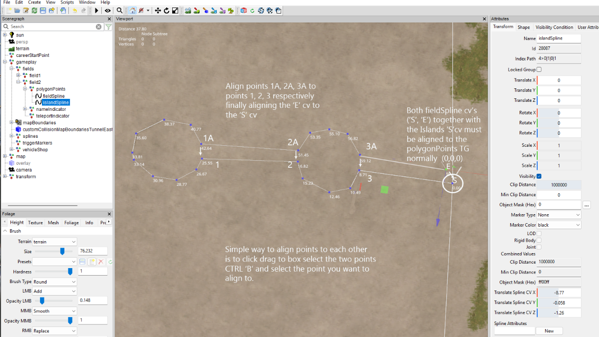
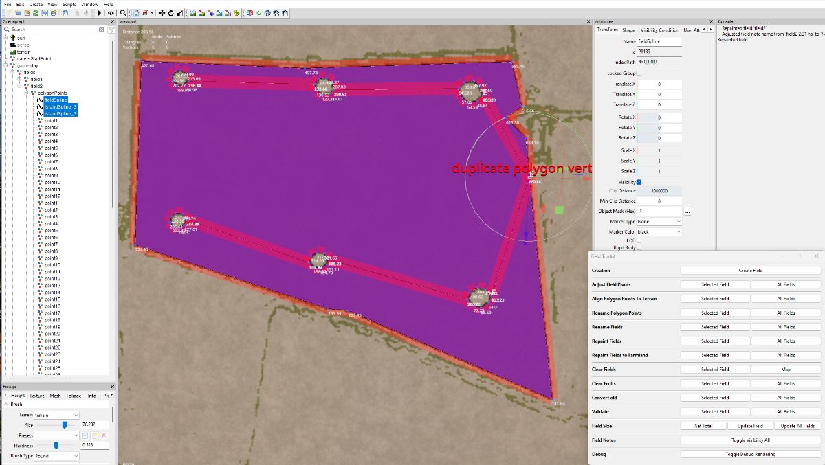
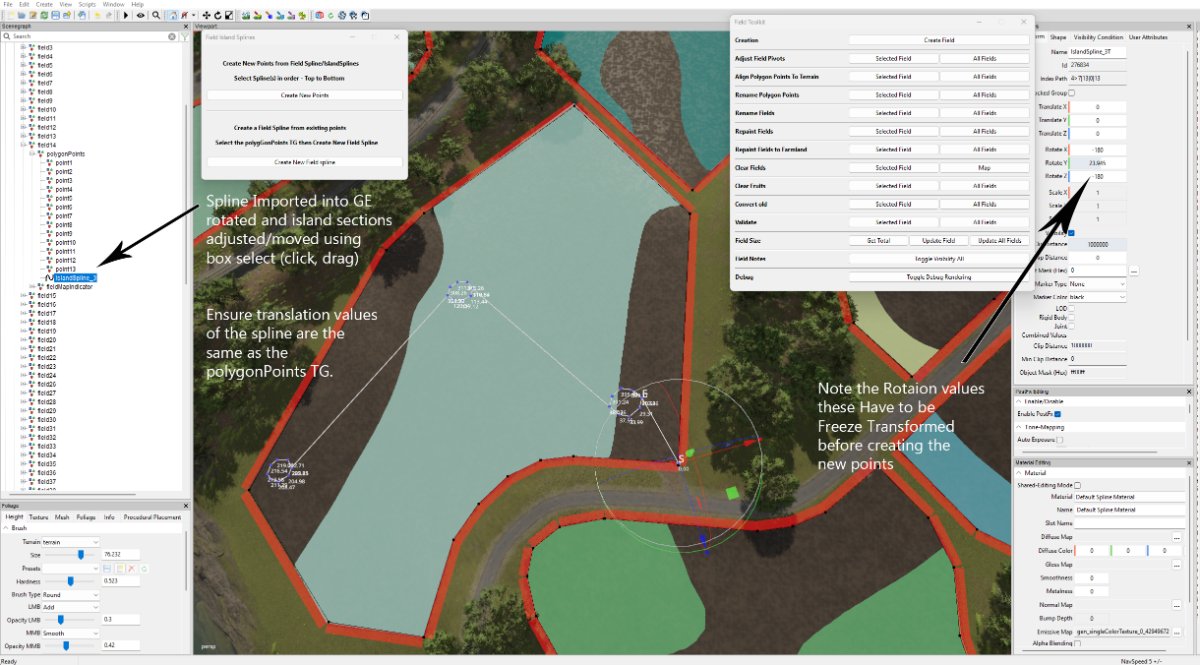
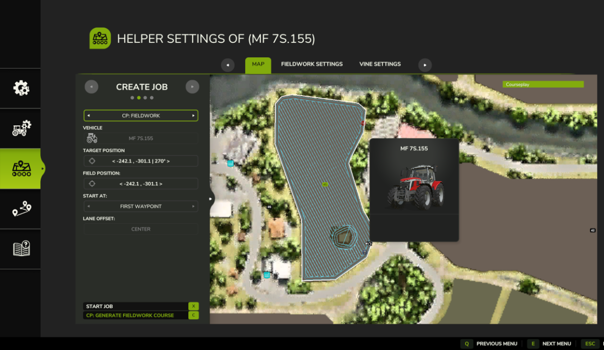
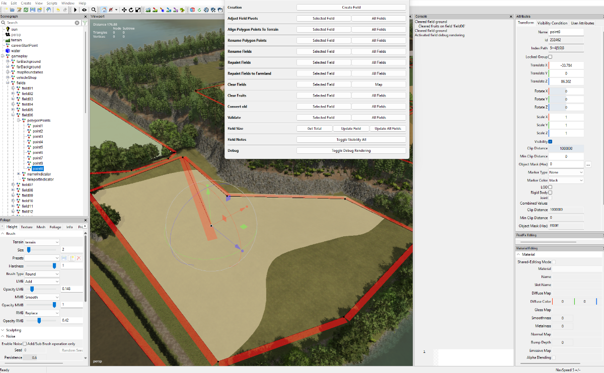
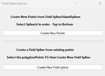
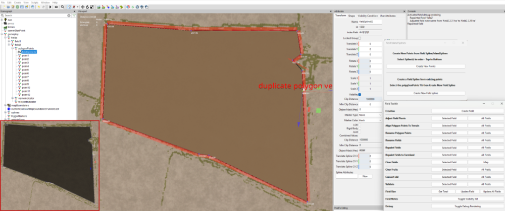
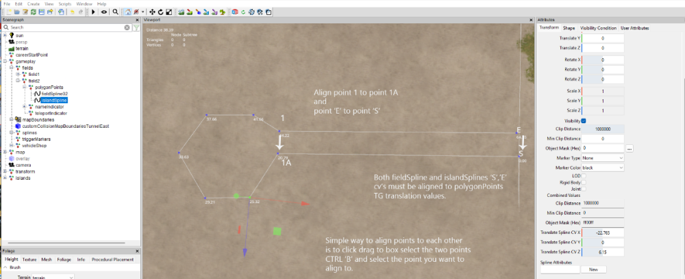
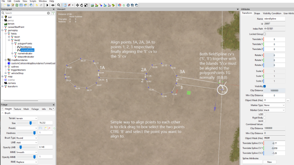
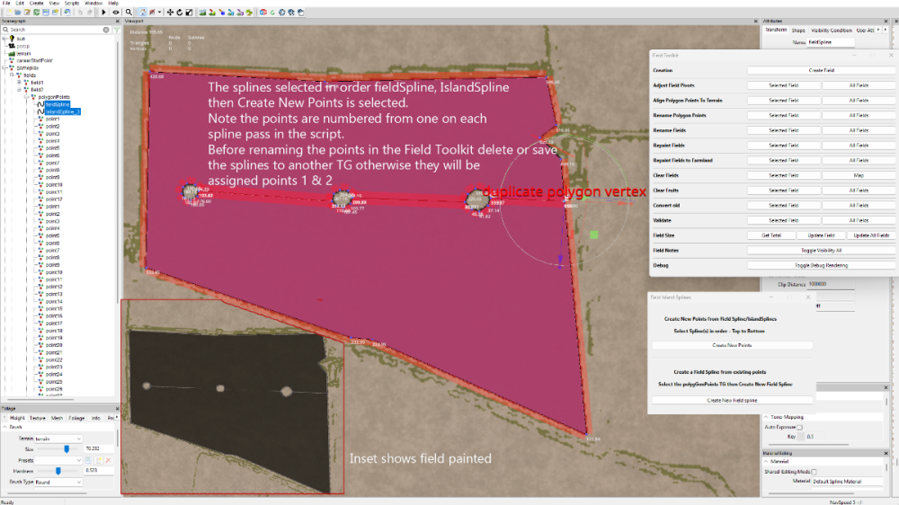
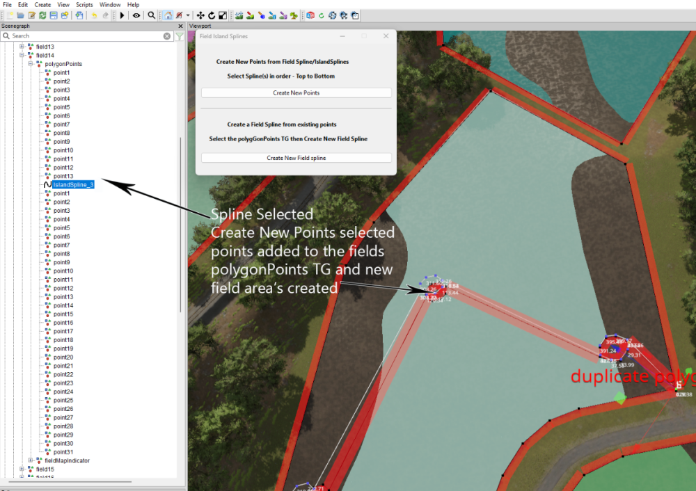
This tutorial will show how to create fields with/without islands using the Field-Island Splines script in conjunction with the GE Field Toolkit (Scripts –Shared Scripts– Map – Farmland Fields – Field Toolkit). Download the Field-Island Splines zip file (found at the bottom of this tutorial) and unzip, place the script in the following folder Download the Field-Island Splines zip file (found at the bottom of this tutorial) and unzip, place the script in the following folder C:/Users/******/AppData/Local/GIANTS Editor 64bit 10.0.4/scripts (replacing ****** with your computer name) Field-Island Splines script This script is in two sections the top panel section ‘Create new points from FieldSpline/IslandSplines’ is used for creating fields with or without islands it basically works by using a spline to create the field edge then using a second spline to create island shapes and when the Create New Points is selected it creates a new list of polygonPoints in the polygonPoints Transform Group. If creating a field with islands then the field and island splines must be selected in order, top to bottom, if only creating a field then just select the field and Create New Points, field creation can then be carried on using the GE Field Toolkit. The bottom panel section ‘Create new Field Spline from existing points’ is used when modifying existing fields, because of the different ways some fields are created (when adding Islands points placement accuracy is important) it may be necessary to create a new fieldSpline from the original polygonPoints . When Create New Field Spline is selected a new fieldSpline ( with the name of the current field ) will be created using the existing points and placed in the polygonPoints Transform group the original points can then be deleted. Because some base game mod maps fields do not close the spline correctly when the script is executed (Create New Field Spline) the script will automatically add a new final point at the same location as the ‘S’ cv, so effectively closing the spline. Islands can be created in any shape and once created saved in a separate folder so creating a ready made album of different shaped islands that can be used in any field. The following sections show how the script can used. Creating a Field with Islands from scratch When inserting points one quick method is to select CTRL ‘B’ and select the cv with the left mouse button, keeping the left mouse button pressed move to the next placement point and press Insert repeat until shape completed Open GE and select Scripts –Shared Scripts – Map – Farmland Fields – Field Toolkit to activate the Field Toolkit panel In the Scenegraph select the fields Transform Group (TG) (gameplay –fields), in the Field Toolkit pop up select Create Field a new field will be created in the fields TG (numbered in the next available value) in this case field2 (this is the field that will be created first in this tutorial), also in this TG is the polygonPoints,nameIndicator and teleportindicater transform groups. Selecting the fields2 TG , CTRL ‘B’ , left mouse click to place the fields2 TG at the entrance of your field ,the Field Notes panel will obscure the actual placement so in the Field Toolkit under Field Notes select Toggle Visibility All to turn it off. When placing fields it is best to place the field TG at the entrance to the field and move the fieldMapIndicator to the centre of the field if required and leave the teleportindicator at the field entrance Select the polygonPoints TG and delete all the points. In GE Select Create –Spline and cut/paste into the polygonPoints TG (do not middle mouse drag as it will assign new translations to the spline) name this spline fieldSpline02 (to avoid confusion when more than one spline is used) in the Attributes Panel -Shape Tab change the Spline Type to Linear this spline type is the same format used by the Field Toolkit when creating fields. Ensure you have the Translate Spline CV panels in the Attributes Transform Panel if not then Select – View – Show – Physics Selection – Enable All , the Translate Spline CV panels is required as some of the cv’s require accurate placement for the fields/islands to work correctly Select the ‘S’ cv and delete it -- This will align the start of the spline to the polygonPoints TG (0,0,0) Select the ‘E’ cv and working clockwise place the spline around the edge of the field (using the method described earlier) place the final point as close to the ‘S’ cv then in the Translate Spline CV panels set the X, Y, Z coordinates to 0 (zero) this will place the ‘E’ cv exactly on the ‘S’ cv (there is no need to close the spline), accurate placement is required otherwise problems will occur with the field generation. Field Spline If just creating a field then Select the spline – Select Scripts –User Scripts -Field-Island Splines and Select -Create New Points a new list of points will be created in the fields transform, delete or save the spline to another TG and carry on with the field creation using the Field Toolkit in the normal way. Image below shows the spline selected, script executed , Toggle Debug Rendering activated, Align polygonPoints to terrain (this also calculates the new field size) and the insets shows the field Repainted and the various log entries. Single / Multiple Islands Create a second spline cut/paste into the polygonPoints TG (immediately below the fieldSpline ) and rename it to islandSpline, (again in the Attributes Panel -Shape Tab change the Spline Type to Linear ) then delete the ‘S’cv as detailed above. With the ‘E’ cv selected draw out your shape (using the method described earlier) the images below show the creation of both single and multiple islands. Single Island Multiple Islands The following image shows a fieldSpline and a three island spline (islandSpline_3) being used to create a field with three islands (suitable for power/pylons installation) In the following image I have duplicated the islandSpline_3 and moved the islands individually to different parts of the field by box selecting (click drag) one of the islands and moving it by the translation gizmo ( if box select is used Ctrl ‘B’ will place all points at the same location) to a different position, then with the spline selected freeze transform any rotation value that has occurred during the island moving, repeating the method for the other islands before selecting Create New Points. The splines have to be moved (to another TG or deleted) before Aligning or Renaming the polygonPoints otherwise they will become point 1,2,3 respectively Then In the Field Toolkit panel Align Polygon Points to Terrain - Select – Selected Field Rename Polygon Points - Select – Selected Field Repaint Fields - Select – Selected Field Validate - Select – Selected Field Note: If you have a duplicate points warning in the console log then delete the duplicates and Rename Polygon points. Modifying Existing Fields For this part I will be using a US map created by the New Mod from Game option but the method should work with other maps, I will also be using the island_3 spline from the previous section. With the field TG (in this case field14) selected, in the Field Toolkit Panel- Select Clear Fields (Selected Field), Clear Fruits (Selected Field), this should clear any terrain detail paint and any crops associated with this field. With the island_3 spline imported into the map cut/pasted it into the polygonPoints TG and then adjusted by the box selecting (click drag) method to suit the proposed new layout Important, when adjusting the island sections ensure that they do not overlap or intersect with any other part of the spline otherwise problems will occur when the new field/island boundaries are created. The image below shows the initial creation of the new island’s layout, the spline was rotated to suit the new layout , this rotation must be Freeze Transformed –(Edit – Freeze Transformations –Rotate) ensure that only the Rotation box is ticked if the Translate box is ticked deselect it. Next with the spline selected, in the Field Island Splines panel select the Create New Points button this will create the new points from the spline and place them in the polygonPoints TG below the spline (Fig. 2) Fig.2 The final steps are as follows, Cut/Paste the spline into another place (TG) in the Scenegraph (otherwise it wil be renamed as a point and cause problems ingame) In the Field Toolkit panel Align Polygon Points to Terrain - Select – Selected Field Rename Polygon Points - Select – Selected Field Repaint Fields - Select – Selected Field Validate - Select – Selected Field Note: If you have a duplicate points warning in the console log then delete all of the named points and Rename Polygon points. Save the map and open in Game, below is an image of the farmlands panel and the islands with a Courseplay course confirming the new island layout. Field Island Splines.zip


 2 points
 -
Apologise I have added the wrong version to the zip file will upload a new zip file tomorrow (09/08/25) as I have updated some of the other FS25 Scripts. Whilst testing the script I have come across a slight problem where the poles may not rotate enough (usually caused by a tight curve in a cubic spline ,sharp angle if using a linear spline) so causing the wires to crossover The soloution ( with thanks to @antler22) is to 1. Run the script with no. wires set to 0 2. Rotatet posts/poles so a better angle is created between the preceding and following posts 3. Rename last post/pole unique so you know where pole placement starts over (for examlpe pole1_A) 4. Run script again with wires set at desired level, this will put wires against all previous posts as well as new ones Delete second set of posts after marked end, as these are now redundant Works for fences as well Edit 15/06/25 This problem along with the upright problem has been solved in the latest version of this script 15/06/25 and is available at the beginning of this topic1 point
-
Added updated FS25 Script Versions Zip This contains an updated Fence Power PLacement script (fixed some bugs) and a new Spline CSV Creator Panel OBJ_25 Spline CSV Creator Panel OBJ_25 ChangeLog Script operation is the same output has changed slightly A new CSVSpline transform group is automatically created in the Scenegraph and the new CSV spline is created in this TG. The new CSV spline ,spline.obj and csvData.txt are still added to the CSVData folder in the maps folder (same place as the map.i3d )which now has1 point
-
Version 15.05.25.01
36 downloads
Auto fermenting silo. This silo is in the silo category, material is converted instantly, it is not a factory. This silo will automatically convert grass, hay, straw, chaff, and wood chips to silage. Cost 50,000 Capacity 10,000,0001 point -
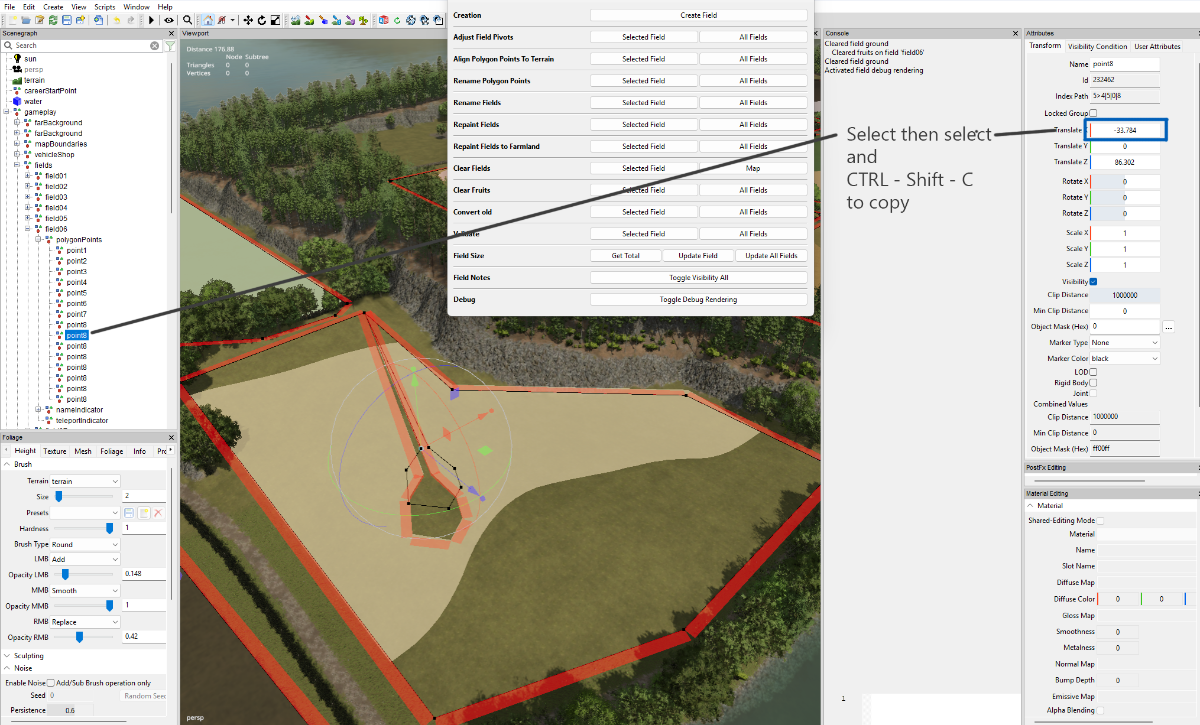
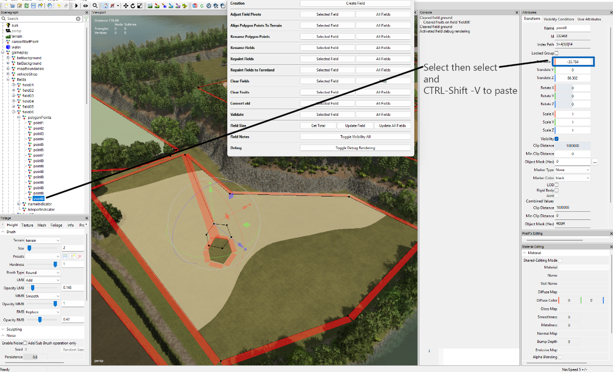
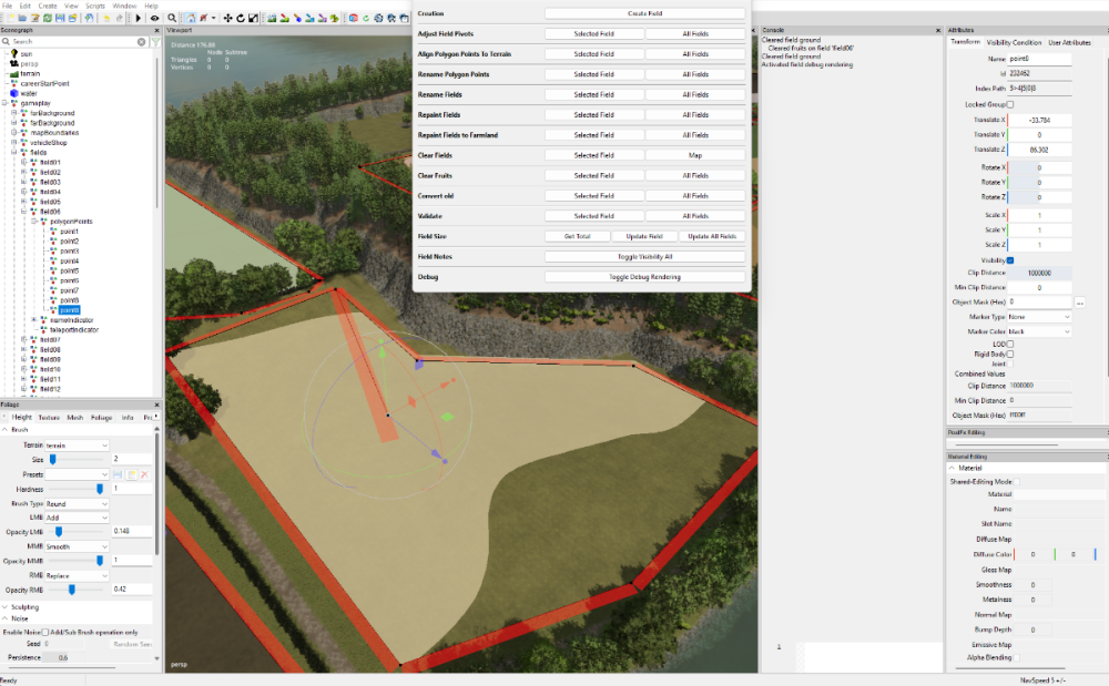
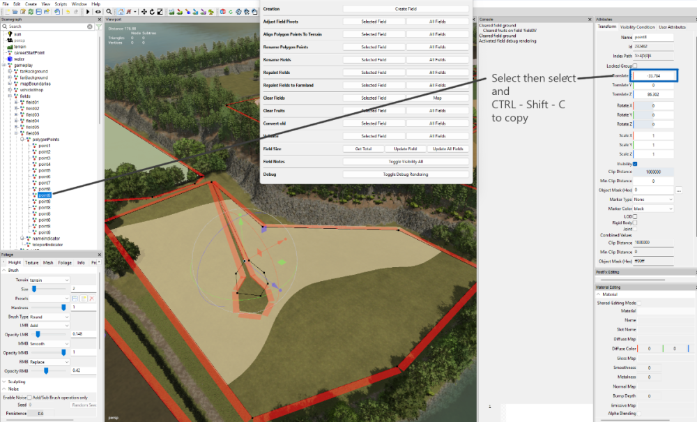
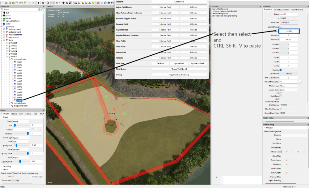
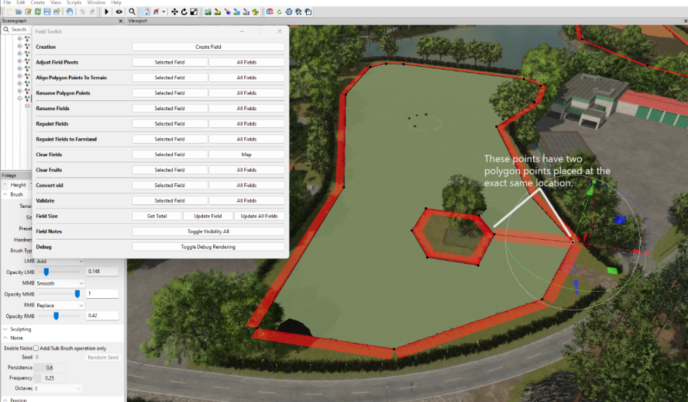
Having done a bit of research and testing using the method in the video it would seem as long as it is done correctly there are no problems when using the AI or Courseplay as the following video and images show. AI Island.mp4 If modifying aan existing field then First select the field in the Scenegraph -- in the Clear Fields (Selected Field) and wait for the field to be cleared (back to underlying texture) then Clear Fruits(Selected Field) Debug Toggle Debug Rendering Select the last Polygon point (note first and last points share the same location) points have to be selected/created in order Ctrl 'D' to duplicate, Ctrl B to place continue until you have the desired shape and the last point is over the first duplicated point To get it aligned perfectly select the 'X' transform in the Attributes panel and Ctrl - Shift 'C' (to copy x,y,z translations) select the last point and then the 'X' translation panel and Ctrl - Shift -V to paste the copied coordinates into it. Select the field No TG - Align Polygon Points to Terrain (Selected Field) followed by Rename Polygon Points (Selected Field), Repaint Fields (Selected Field), Validate (Selected Field) In the console log you will see that the field size has been adjusted to suit the new layout The problem with the method in the video with lines all over the place appears to be not aligning the first and last duplicated point correcrtly Image below show the various steps

 1 point
 -
This script can be modified by yourself to allow decimal entries to the offset by following these steps Open FS25 Spline Modifier.lua in GE script Editor and navigate to line 78 local offsetSlider = UIIntSlider.new(offsetSliderSizer, offset, -25, 25 ); replace with the following line local offsetSlider = UIFloatSlider.new(offsetSliderSizer, offset, -25, 25 ); Save and exit the Script editor Execute the script from the Script - Users Scripts menu you should now be able to enter a decimal value for the offset Offset max min values have been reduced to avoid distortion caused by inner and outer radius when setting high values. An updated script is currently being created and tested.1 point
-
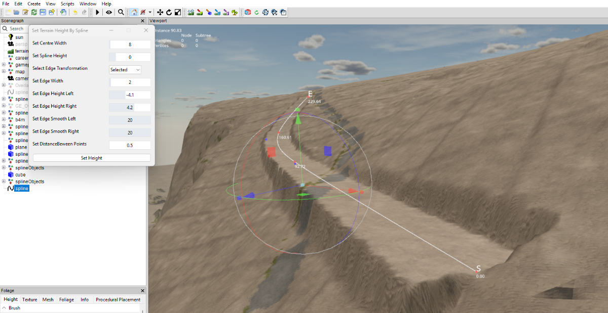
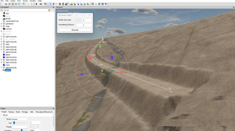
Comparison between my version and GE version of Set Terrain Height scripts with basically the same settings. My version GE version As you can see the GE version smooths the vertical drop and heights better

 1 point
 -
Sorry I should have been more explicit, this script is for FS 25.1 point
-
The only thing I can say to you, the creators of these scripts, is that you are truly incredible. Congratulations and thank you so much for helping the community from the bottom of your hearts!1 point
-
You could try this modified from this post https://gdn.giants-software.com/thread.php?categoryId=4&threadId=15656 setAudioCullingWorldProperties(-8192, -100, -8192, 8192, 500, 8192, 16, 0, 0); setLightCullingWorldProperties(-8192, -100, -8192, 8192, 500, 8192, 16, 0, 0); setShapeCullingWorldProperties(-8192, -100, -8192, 8192, 500, 8192, 16, 0, 0); or setAudioCullingWorldProperties(-8192, -100, -8192, 8192, 500, 8192, 16, 0, 9000) setLightCullingWorldProperties(-8192, -100, -8192, 8192, 500, 8192, 16, 0, 9000) setShapeCullingWorldProperties(-8192, -100, -8192, 8192, 500, 8192, 16, 0, 9000) from https://gdn.giants-software.com/thread.php?categoryId=4&threadId=15658 or this one for 16x maps -- Author:jcalv -- name:JuotcaX16RandSolved -- Namespace: local -- Description: -- Icon: -- Hide: no -- AlwaysLoaded: yes setAudioCullingWorldProperties(-4096, -100, -4096, 4096, 500, 4096, 16, 200, 1000) setLightCullingWorldProperties(-4096, -100, -4096, 4096, 500, 4096, 16, 200, 1000) setShapeCullingWorldProperties(-4096, -100, -4096, 4096, 500, 4096, 64, 200, 1000)1 point
-
Updated Spline Paint Panel script -- 20/01/2025 Random value problem fixed and UI Changes1 point
-
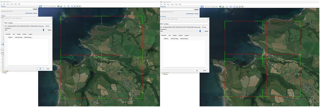
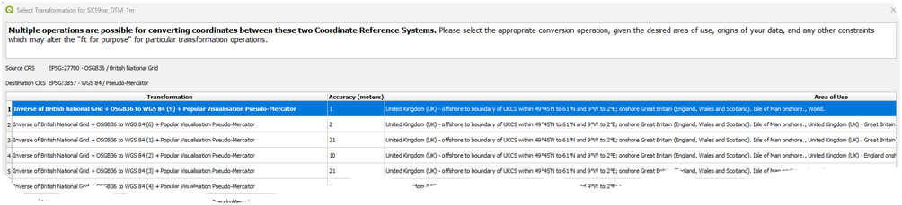
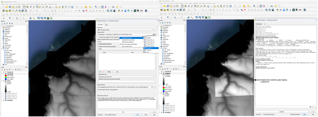
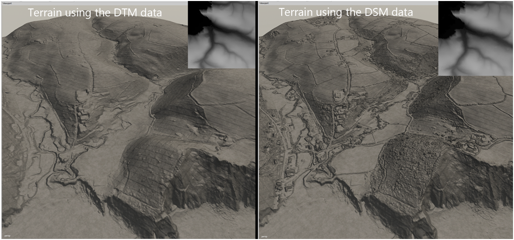
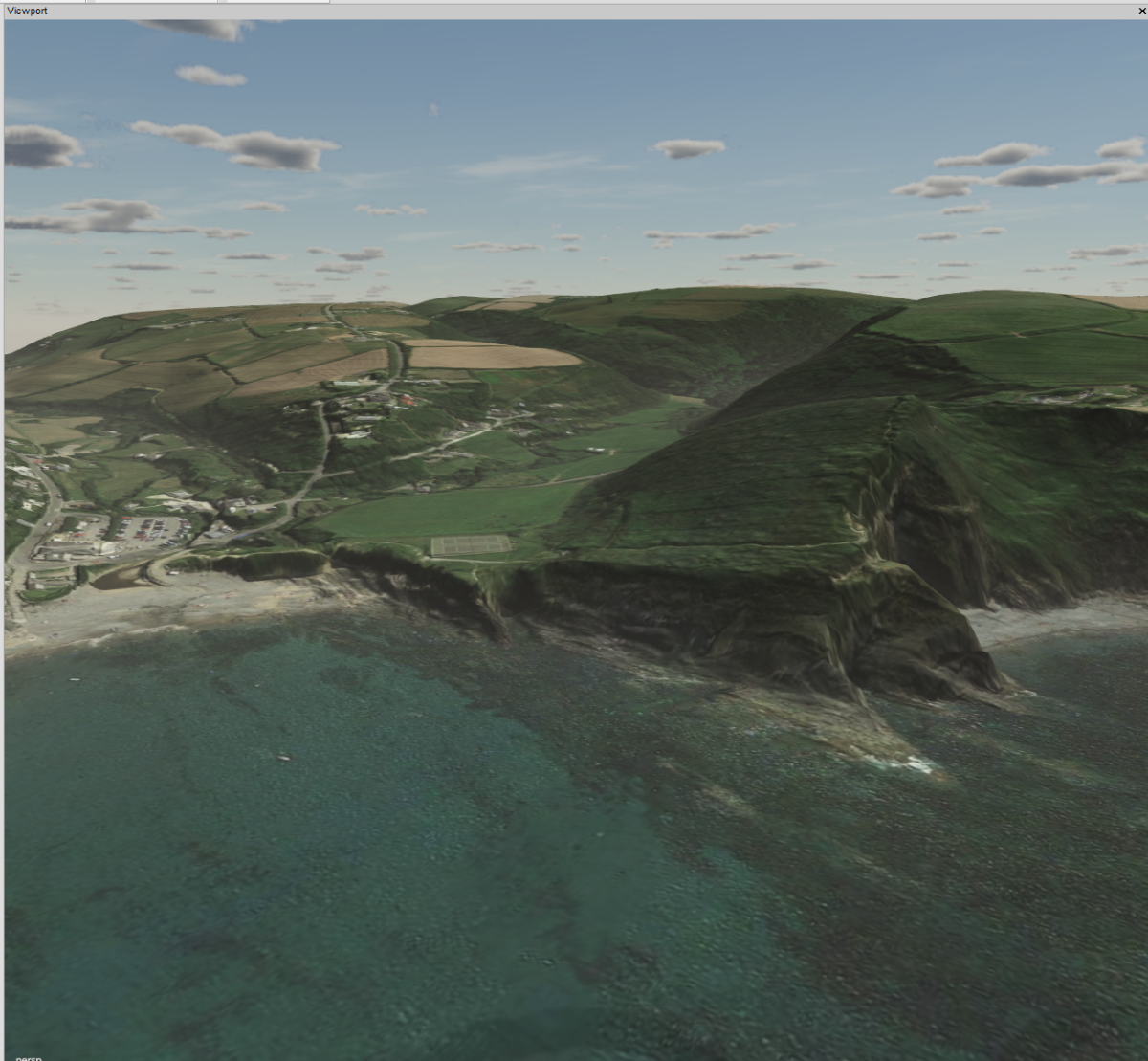
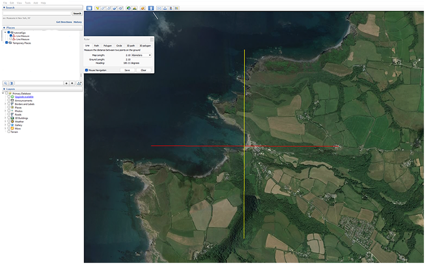
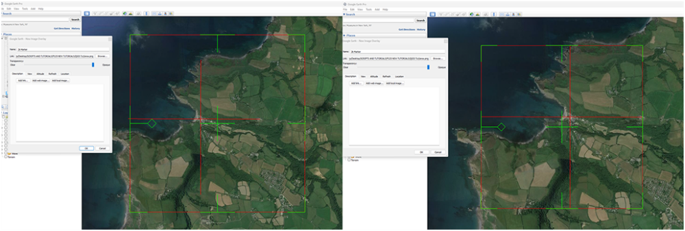
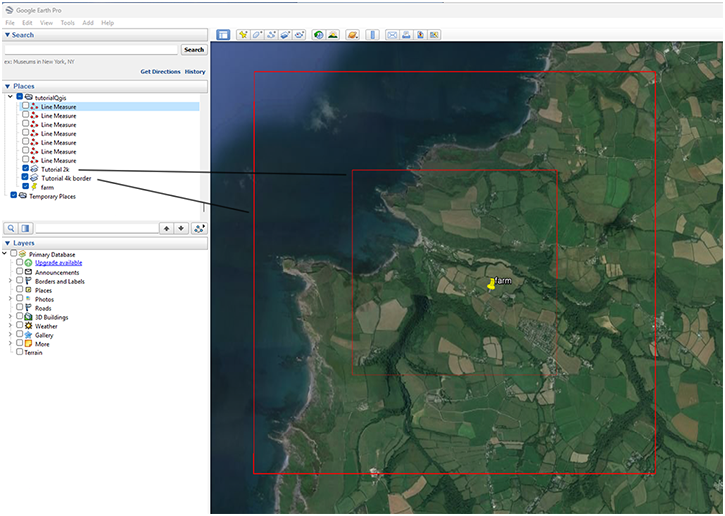
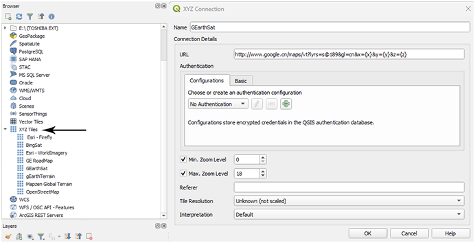
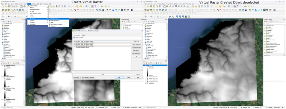
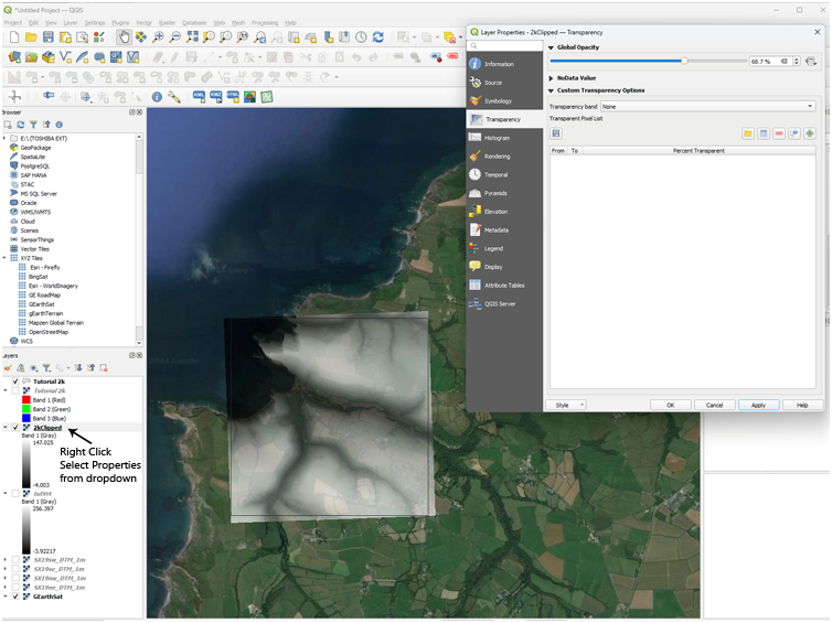
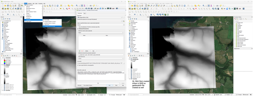
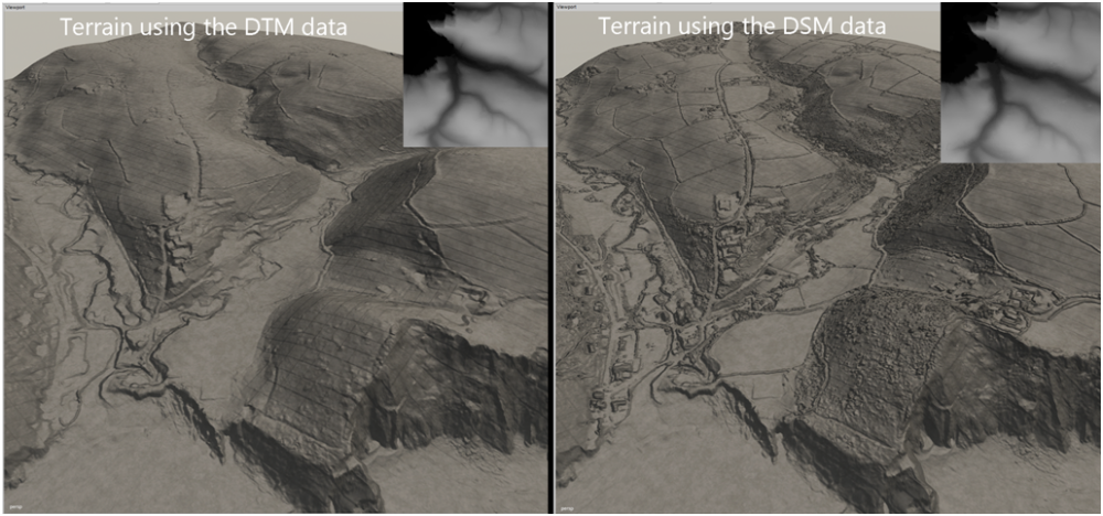
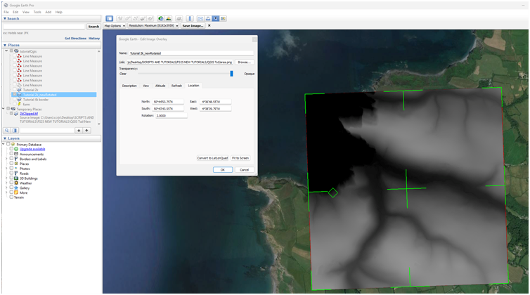
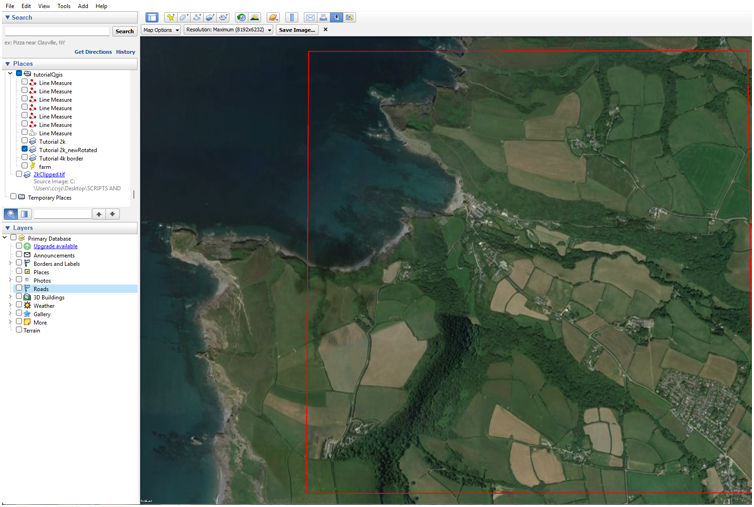
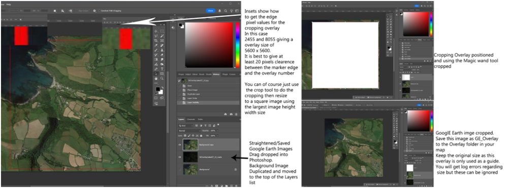
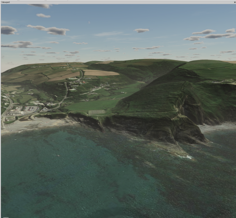
DEM Creation using QGIS Tutorial For this tutorial you will need the following programmes and items Google Earth Pro --- https://www.google.com/earth/about/versions/#earth-pro QGIS --- https://qgis.org/download/ Overlay.zip --- Attached at the end of this tutorial Download Google Earth Pro and QGIS (may take a while as QGIS is approx 1.2Gb) Unzip the Overlay.zip and place the Overlay folder into you map root folder Create Farm Marker This section details how to create a marker that outlines your proposed farm area for use in QGIS and is basically the same as first part of the previous tutorial, DEMs and Borders the Easy Way. Once both programmes are installed open Google Earth Pro – Select the Temporary Places icon and right click any where in the Places panel, Select- Add –Folder name this folder with your map name (this is to keep all your files in one folder). You may need to drag drop any newly created files into this folder. Ensure the Terrain Icon in the Layers panel is deselected Navigate to your proposed farm location Create a vertical and horizontal 2.1km line using the ruler tool centred roughly at the middle of your proposed area Select the Add image Overlay icon in the Toolbar (green markers will appear) and browse to the Overlay folder location and Select Area.png, rename to 2k Area don’t close the Image Overlay pop up at this time. You will see a red square with green markers, adjust the edge markers (T shape) to fit the horizontal and vertical lines previously made this will give you a 2.1k square which you can move over the location to finalise the area by means of the centre cross or rotate using the diamond (if you move any of the corner markers you will distort the square and have to reset the edges). Once you are happy with the position click OK. If you wish to move it again right click on the 2k Marker in the Places panel and select Properties this will bring the adjustment markers back. At this point mark and name the area using the Add Placement tool as when adding the Lidar Data/SRTM Google Earth zooms right out so the Markers may not be visible for you to centre the cursor on to scale the relevant Geo.tif Should you wish to create a border around your 2k area then, using the ruler tool create 1k lines away from the edge of the 2k area. 1k chosen for performance reasons but if you want a bigger border just increase the distance. Select the Add image Overlay icon in the Toolbar and browse to the Area.png location and select it, rename to 4k Border and repeat the alignment detailed above. In the Places Panel right click the 2k Area icon and Save Place As .kml (in a suitably named folder) do the same for the 4k Border Area if needed. Obviously if creating a larger map change the markers to an appropriate value. The Line Measures can now be deselected leaving just the two markers Finally save the My Places -- File – Save – Save My Places Creating the DEM Different Countries will have different methods of downloading data so check the relevant Sites methods. For this tutorial I will be using UK Lidar Data available from -https://environment.data.gov.uk/survey Open in browser zoom in to your location Select Draw polygon, Draw polygon round the farm area (right click move to next point until your shape is complete double click to finish) Select - Get Available Tiles Select Product --LIDAR Composite DTM --- This produces a ‘terrain only image’, DSM will produce all buildings trees etc image. Select Year -- Latest year currently 2022 Select Resolution – 1m - higher 2m resolution will have smaller file size 1m resolution files will have a file size of approx 80kb per tile. Select - Download All and save to a suitable folder (the one you saved the 2k/4k Area .kml’s) Create another folder in that folder and name it Your Farm Name Tifs Unzip the downloaded files and copy paste the DTM_1m.tif images into this folder. QGIS I will be using QGIS 3.40.0 throughout this section later versions may become available so version numbers may change. All the programmes required for QGIS should in a folder on your desktop after installing QGIS 3.40.0 In the folder QGIS 3.40.0 select QGIS Desktop 3.40.0 In the Browser panel check to see if you have a Google Earth overlay in the XYZ Tiles icon ( this overlay will only be used as a reference). If you do not have the Google Earth Satellite overlay then right click the XYZ Tiles icon and select In the Pop up panel enter a suitable name (eg Google Satellite) and in the URL panel copy paste the following http://www.google.cn/maps/vt?lyrs=s@189&gl=cn&x={x}&y={y}&z={z} the rest of the settings can be left as is and click OK. Should you prefer or want to add others then do the same as above here are some Open Street Map https://tile.openstreetmap.org/{z}/{x}/{y} Bing Maps http://ecn.t3.tiles.virtualearth.net/tiles/a{q}.jpeg?g=1 Google Satellite Hybrid https://mt1.google.com/vt/lyrs=y&x={x}&y={y}&z={z} Other map tiles can be found here, bear in mind some may require an API key. https://www.geohowtos.com/howtos/xyz-tiles/xyz-tiles-qgis In QGIS double click on the Map Tile you want to use, it will open with a complete map of the world, don’t bother zooming in yet. Input Lidar/SRTM Data The following method is the same for both Lidar and SRTM data in this instance I am using Lidar data Drag and drop the Lidar tif image(s) (if more than one select all) into the QGIS main screen they/it will open in the Layers Panel, if more than one then they will be listed separately in the Layers Panel. If you get a Select Transformation pop up as shown below when adding data Select -- Cancel this will keep the original CRS of the data otherwise distortion of the data will occur. Right click on any of the layers and Select- Zoom to Layer, this will zoom to the layer image with the Map Tile reference layer underneath. If only one Layer (Lidar tif image) skip the next section Multiple Layers If more than one layer Select --Raster -- Miscellaneous --Build Virtual Raster At the end of the Input Layers box select the 3 dots icon this will bring up another pop up with a list of all the layers in your Layers panel Select the Lidar tif image(s) then Run A new Layer will appear named Virtual with all the selected Layers merged into one image with the correct brightness/contrast If you want to save this Virtual file for future reference, in the Layers Panel right click on the Virtual entry and Select - Export -- Save As In the 'Save Raster Layer as' pop up Select –Output Mode -RawData Select the three dots at the end of the filename box to open a file browser navigate to where you want to save the file add file name then Select Save and in the Save Raster Layer pop up select OK. Clip the image tif to the 2k (4k) size If necessary right click the new Virtual (or Single) Layer and select Move to Top this will place the image above the Map Tile layer Or middle mouse button select and drag to the top of the Layers panel. Drag the 2k Area.kml saved earlier into QGIS and in the pop up Select Add Layers depending on the .kml/kmz used there may be two Layers one will have the marker colour the other will be the marker shape file it is the shape file that is required for the next step, if both shown in the Layers Panel deselect the one with the three colour bands. Select – Raster – Extraction –Clip Raster by Extent In the pop up panel Input Layer - in the drop down Select the Virtual (single) Layer Clipping Extent --- Select the arrow on the far right, in the dropdown –Calculate from Layer and select the 2K Area shape file Clipped Extent--- Select the Arrow far right and Save to File, browse to where you want to save this file, name the file and Save as Type *.tif All other settings can be left as is Select-- Run The clipped image will not be aligned to your marker but be slightly rotated this is because the marker has a different CRS to the Virtual Layer. This seems to only affect data in the EPSG:27700 - OSGB36/ British National Grid format. If someone a bit more QGIS savy can show how to correct this I would appreciate it. I have tried re-projecting all Layers to both the British National grid and the default Google earth EPSG:3857 but without success and as stated previously converting from EPSG:2700 to EPSG:3857 creates artefacts in the image. Right click the new 2k clipped layer and Select – Export – Save As --in the Save Raster Layer as.. popup Select Output mode – Raw Data File Name – Select three dots icon and navigate to where you want to save the file – name and save Extent(Current:Layer) –Calculate from – in the Layer drop down Select the 2k clipped layer Select -- OK This .tif image will be required if creating overlays, Google Earth/and ones used for positioning (Grass/Asphalt etc). Clip Raster by Extent ref image You can check the new rotation alignment of the clipped area by reducing the Opacity of the layer by right clicking the layer and Select- Properties - Transparency and adjust the transparency slider to suit (transparency will not occur until after OK is selected) and Select OK. You will have to reset the opacity back to 100% before continuing. Create the 2048 x 2048 16 bit Greyscale Dem With the new 2k clipped layer selected, Select – Raster—Conversion – Translate (Convert Format) Input Layer – Clipped 2k Area Assign a specified No Data Value to output bands (optional) -- setting done by Additional command line parameter i.e. ‘-a_nodata None ‘ Additional command Line Parameters -a_nodata None - This will set any blank/transparent data to black -scale Min Max 0 65535 (Min, Max Lowest ,Highest value in the virtual Layer, 0 65535 means the whole greyscale range between 0 and 65535 will be used to represent the height values) -outsize 2048 2048 -- this is the output image size e.g -a_nodata None -scale 0 264 0 65535 -outsize 2048 2048 – do not forget the – at the beginning of each command else you will get Error messages Output Data Type – Select UInt16 in the dropdown Converted – Select icon on the far right and in the dropdown –Save to File Browse to where you want to save the file, Name and Save as Type PNG files (*png) This file can then be copy/pasted into your map data folder and renamed as dem.png without any further modification. Resultant Dem images and Giants Editor images for both the DTM and DSM data The Grid lines in the images appear to be being caused by Giants Editor 10.0.3 (don’t show with same image in GE 9.0.6) Whilst there is more detail in the DSM version it also means more smoothing/flattening of the terrain when placing items Creating the Overlay.(Google Earth and an Image editor required) This is just for the Google Earth overlay as in the new Giants Editor it is possible to overlay the image on to the terrain using the terrain decal setting in the Shapes Tab. This method is for the EPSG:27700 - OSGB36/ British National Grid Lidar data -SRTM data may not require any adjustment so skip to Saving Image Ensure Terrain is deselected in the Layers Panel Drag drop the previously saved 2k clipped .tif into Google Earth Select the 2k Area in the Places Panel and right click copy/paste it into the same folder rename to 2k Overlay. Right click the 2k Overlay and Select - Properties and adjust the rotation/alignment to match the 2k clipped.tif (I find it easier to do the rotation adjustment via the Location settings in the Google Earth –Edit Image Overlay panel which allows for finer rotation movements) Once aligned Select- OK in the Edit Image Overlay pop up. Marker Rotated and aligned to the 2k clipped.tif Saving Image. Select the Save Image Icon and zoom in to the 2k area so the marker top/bottom close to map image edges. Deselect the 2k clipped icon in the Places Panel, if your marker has any rotation you can either adjust it in Google Earth or later in the Image Editor. (I tend to align the top marker line with the border edge) Select - Map Options and deselect all options. Select – Resolution Maximum and Save image in the pop up name and save in a suitable location – this will be basis for the Google Earth Satellite Overlay image. Marker aligned to edge of Google Earth border Image Editor Any Image Editor will suffice I will be using Photoshop (crimbo present) otherwise I would still be using my free legacy version of Photoshop CS2 which does almost everything needed for Giants Editor/Farming Simulator creations with just a couple of free plugins. https://www.techspot.com/downloads/3689-adobe-photoshop-cs2.html Drag/drop the Google Earth image into the image Editor Duplicate the Google Earth image and move to the top of the Layer list, the original Background Image can now be deleted. Cropping the image for the overlay, there are two ways of doing this The easiest is by using the cropping tool and adjust it so it is just inside the marker edges then crop and resize the image to the largest Height/Width value. The second is by creating an overlay that fits inside the marker and using this to crop the image, for this you will need to have the rulers set to pixels. Zoom in to the left hand marker edge and note the pixel vale about 20 pixels from the edge of the marker do the same for the left hand marker edge subtract the lowest from the highest and create a new image of this size and fill with colour (any), copy/paste into the Google Earth image and adjust to be inside the marker edges, when satisfied select the new image with the Magic Wand tool and select Image - Crop. Save the cropped Google Earth Layer as GE_ Overlay.png and place it in the Overlay folder (replacing original), keep the cropped size as this is just used as a guide, you will get size errors in the log but these can be ignored. Once the Ge_Overlay.png image and dem.png are placed in their relevant folders open Giants Editor and import the overlay.i3d into the Scenegraph adjust the height of the overlay to match the terrain height, the following image shows the result (dem is the DTM version) Note: The image is aligned to all the terrains 'lumps/bumps' roads/cliffs etc Should you wish to create additional overlays/markers using dirt/grass asphalt weight textures or border meshes then please refer to the Overlays section in the DEMs and Borders the Easy Way tutorial Overlay.zip


 1 point
 -
Check the originators Github https://github.com/ZenJakey/fs25-scripts/tree/main1 point
-
Thank you very, very much for your time and effort, its just what we were looking for, it is brilliant now we have a great grounding in Procedural Placement to work from using this example. I will now spend a couple of hours watching your full tutorial on youtube and look forward to any more FS25 tutorials you may have in the pipeline.1 point
-

Version 08.12.23.01
931 downloads
Update 08.12.23.01 Added decal color so that they are not switching material with design. Update 07.12.23.01 Magnon Windrow BD Version 07.12.23.01 Per request by Truzedo I have made some changes to this mod. I usually don’t add huge capacity options, but I have had several requests and have seen many streamers with edited versions. So here you go. Major update I suggest selling your old one before adding this version. It should convert over, but you may lose material or get some initial warnings. There are 4 capacity and unload speed options, each option has to be selected independently in the store. I also added decal color selection and the ability to change material and color on the base and design parts. Materials are steel, chrome, stainless, brushed steel, plastic. Base Cost 132500 Option to add or remove windrowers no cost (windrow effects) Capacity 50K - Free 100K – 2000 500K – 10000 1M – 70000 Discharge options free (when matched up correctly the unit will empty in around 10 seconds) 5K LPS 10K LPS 50K LPS 100K - LPS Update 26.12.22.01 Lowered ground ref to help issues with pickup. Update 22.12.22.01 Added the ability to remove windrowers. If you already have one of the units purchased you should be ok I just suggest after inserting the update that you open the game, save the game, then open again. The first time opening your game save you will receive some warnings about effects and the windrowers will not show effects, however after the save and reopen the warnings will go away and everything will work. Update 30.12.21.01 Made loading area for silage additive a little larger for production of silage additive in the fermenting pack added on 30.12.21 The loading wagon is live!!! Huge thanks to Grabby again for testing along the way. Also I would like to be sure to thank HungryCow Design for making the second windrow array image for me, without it I would not have been able to get effects to work on both sides. Another side note. This isn't my original idea. I found a wagon from FS15 that I believe dates back pre FS13 called the drake wagon. This loading wagon is based off that beast. This is the Magnon 530 with some bd upgrades. It has the option of 200,000 capacity with or without silage additive, or 500,000 with or without silage additive. I have added the windrowers everyone has loved in the past however in FS22 I decided to add windrow effects. The effects will only work for hay, grass, and straw. The wagon picks up silage, straw, hay, grass, and chaff.1 point -
@jdunn1019 With regard to the splineSurface 'mesh' if you apply a texture to it and adjust it to any shape you want by selecting and dragging the points then in the shape tab select terrainDecal you will get the texture and shape applied to the terrain following the terrain contour, downside is the texture will be stretched. Select Insert to create more points, Delete to remove, holding shift whilst selecting points allows you to move all the selected points in the x,z direction you chose. So I suppose it could be used for creating defined paths/roads I dare say others will have different methods/uses of it, it would be nice to have a bit more definite information from Giants regarding these new features of GE.1 point
-
IT's SO BIG! I like the collecting effect. Good job BdBssB. Thanks.1 point
-
Even if you could scale a spline I don't see how it would help in your case because scaling would affect the whole spline so you will still have the different distances between them that you already have albeit larger or smaller. As I see it your options are , adjust them manually or try using the Create Duplicate Offset Splines script (it has been updated for FS25) which would mean deleting some of the splines you have already created, looking at your image this option would only affect one spline anyway.1 point
-
Yes thanks jdun. I don’t have the time to do it that’s for sure. Huge thanks to @administratorand @WrinkleysRulefor all your contributions to this site.1 point
-
Ok I changed the settings to get a more random scale but I will now revert to the previous settings in the next update, which will be after I sort this rotation problem. In the meantime if you want to change the settings in GE script editor line 226 has the random scale section Replace -- sx = scaleLow + math.random() * scaleHigh with local scale = scaleHigh - scaleLow sx = math.random()*scale+scaleLow1 point
-
Scripts now updated and available here1 point
-
Apologise profusely, I have found an error in the script and will update the splinePlacementPanelCombined_25 script later today. Problem was caused by the Random Scale settings some trees were given a scale of '0' with Scale Low (Min) set below 1 so were placed but invisible. Script will be updated later as I have an update to do to the Fence Power Placement script also.1 point
-
I did find an easier way to do this, not sure why I didn't think of it before. But for any curious... Run the script with no. wires set to 0 Adjust posts/poles to preferences (sharp 90deg corners) Rename last post/pole unique so you know where pole placement starts over Run script again with wires set at desired level, this will put wires against all previous posts as well as new ones Delete second set of posts after marked end, as these are now redundant1 point
-
I realise it must be hard to keep on top of all the spam/bots to keep the site clear and occasional problems will probably still occur. It was a bit of a shock but thank you for all your work as I know you have have had some seroius medical episodes but once again thank you very much for your efforts in running this site. 🙂😊😊👍👍👍1 point
-
@Mister Laptop Attached is a simple script that will align trees to the terrain, place in C:\Users\Your Computer Name\AppData\Local\GIANTS Editor 64bit 10.0.3\scripts To use Select the Transform Group containing your trees and execute the script LIMITATIONS The individual tree TG group must be formed as below i.e. TG containing your Trees | pinusSylvestris_stage03 | oak_stage03 etc Also the script will only place the trees TG at the terrain height if the trees LOD is set at a different height to its TG group the script may not work as intended. Obviously the trees point of origin must be at the base of the tree A print out of the number of trees parsed and the number changed will appear in the Console Log Align trees to terrain.lua1 point
-
Not at the moment as I am still trying to workout how the new system works, apparently there are further updates from Giants in the pieline regarding this script1 point
-
NOTE: These scripts are personal edits of original scripts by various authors ( Stegei, Evgeny Zaitsev, Nicolas Wrobel,TracMax and W_R ) and posted on the FarmerBoysModding site for members of the FarmerBoysModding community's personal use and not intended for any general public release. Furthermore they are posted on the understanding that NO monetary gain whatsoever,regardless of source can be made from all or parts of them by any person(s). Including but not limited to, Patreon, soliciting for or requiring donations for work done for any purpose, posting on a website that gives any form of remuneration per download or view. Copyright remains with the original creators of these scripts. It would appear there has been some confusion with the new and old versions of these scripts so to avoid any confusion delete any previous versions of these scripts before installing these new versions and read the New Tutorials relevant to the script you are using. 24/05/23 --- Newer versions of these scripts available here Installation First a big thank you to Stegei, Evgeny Zaitsev, Nicolas Wrobel and TracMax the originators of some of these scripts. Whats New All the scripts no longer require the use of the Script Editor and are now executed directly from the script dropdown in GE ,- Select--Scripts The scripts now contain a set of Set Up scripts (Spline CSV Creator Set Up, Terrain Paint Set Up, Terrain Height Set Up and Spline Placement Transform ). These have to be run before using the main script as they create in the User Attributes panel of GE the User Attributes required for each script. They only require to be run once for each spline used whilst editing, also if the map is saved between edits the User Attributes created are also saved to the spline used so the setup script does not have to be run again when the map is opened for subsequent edits. Because of the various changes/updates to all the scripts it is recommended that all previous versions be deleted before installing the new versions. Download and unzip the Updated Spline Scripts.zip, and copy/paste the contents as laid out in the zip directly into C:\Users\Your Computer name\AppData\Local\GIANTS Editor 64bit 9.0.3\scripts The Updated Spline Scripts.Zip contains the following files, a brief description of each follows, further detailed information is contained in the relevant tutorials. Spline CSV Creator Set Up Creates in Giants Editor User Attributes Panel the User Attributes for the Spline CSV Creator script. Spline CSV Creator Creates a new Spline.i3d aligned to the terrain with the CSV distance set by the CSV Distance attribute in the User Attributes panel, also created is a Spline CSV data .txt both are placed in the new CSVdata folder created in the root folder of your map. Requires Spline CSV Creator Set Up to be executed first. Terrain Paint Set Up This script prints the terrain layer textures numerically in the Giants Editor Console log. It also creates in the Giants Editor User Attributes panel the necessary User Attributes for the Terrain Paint script operation.. Terrain Paint For painting along the spline using map terrain textures, different textures can be selectedand painted for the centre and left and right edge areas. Requires Terrain Paint Set Up to be executed first. Terrain Height Set Up Creates in the User Attributes panel of Giants Editor the necessary User Attributes for the Terrain Height script Terrain Height Allows for setting the terrain height using a spline and has independent height settings for centre width, left and right edge width. Requires Terrain Height Set Up to be executed first. Spline Placement Transform Creates a splineObjects transform group with the correct hierarchy in the Giants Editor Scenegraph and in User Attributes panel the User Attributes necessary for the operation of the Spline Placement script. Spline Placement Places objects along a spline at terrain height at fixed or random distances along/around and either side of the spline Requires Spline Placement Transform to be executed first Spline Placement Delete Deletes ALL objects in the placedObjects transform group. ----------------------------------------------------------------------------------------------------------------- Giants Editor Spline Scripts User Attributes Brief description of the various User Attribute settings, further information available in the relevant tutorial. Note: If the map is saved the User Attributes created will be saved (complete with settings) to the relevant Transform Group/Object and will be available when the map is reopened, as such to avoid complications with the save if any of the individual User Attributes are deleted (by selecting the red X) then the next time any of the scripts are run a warning will be printed in the Console log, example below \ WARNING\ ATTRIBUTES ERROR PLEASE RESELECT SPLINE PLACEMENT TRANSFORM The User Attributes will then have to be set up again by reselecting the named Set Up script in the above case the error is with the Spline Placement script Spline CSV Creator script User Attributes created after selecting Scripts-- Spline CSV Creator Set Up Terrain Height script User Attributes created after selecting Scripts—Terrain Height Set Up Terrain Paint script User Attributes created after selecting Scripts—Terrain Paint Set Up The letters in brackets on the left of each Attribute name are there to ensure correct layout if more than one set of spline attributes are set up on a single spline, the script name is also entered to separate the individual Script Attributes, example below. Spline Placement script This script isn’t affected by the multiple attributes problem (shown above) although it still uses the same spline as the rest the Attributes are assigned to the splinePlacementTransform not the spline itself. User Attributes created after selecting Scripts—Spline Placement Transform To avoid errors and having to repeat the various Set Up scripts it is advisable not to delete any of the User Attributes until work has finished using the particular spline after which they can be all deleted if required. Further information available from the tutorials Export a Spline from Giants Editor Into Blender to Create Roads/Railways (Updated) Terrain Height, Paint Terrain and Spline Placement scripts (Updated) Note: Before using any of these scripts on a current Work In Progress (WIP) map, it is recommended that a blank starter map is used to experiment and get familiar with the scripts, settings, executions and results. Read the New Tutorials as the operation and execution of all the scripts has changed. Updated Spline Scripts_18.12.2022.zip1 point
-
The scripts have been updated and are undergoing tests at the moment. They will not be released until after the new game patch as things are likely to change not only in game but in GE so it would be pointless to release them at this time. DEM's and Borders Tutorial On the whole the same method can still be used however the dem size is now 2048 x 2048 16 bit greyscale. If converting an existing 1024 x 1024 dem I suggest you select bilinear as the conversion this will minimise the 'steps', in my test case they appeared as shadows less than 0.2 m high. I am working on a new tutorial for the Dems using Google Earth/QGIS to extract the dem from a SRTM/Lidar image and crop (to chosen area) and export it to a 2048x2048 16bit png which will be ready in due course.1 point
-
England/ part of Northern Ireland dems (lidar 1 or 2m resoloution ) available here https://environment.data.gov.uk/survey Zoom in and draw the polygon around your area by just clicking on the four corners and then select Get available tiles, select product LIDAR Composite DTM select latest year (if choice available) Select resoloution required (1m will give the best resoloution but is a larger file per tile). Once all tiles downloaded copy/paste the .tif image into a new folder and follow the QGIS post on page 4 of this topic. map dem size in FS25 is 2048 x 2048 16bit Greyscale. Looking at the FS25 US map data folder there appears to be two 'dems' one labeled unprocessedHeightMap.png the other dem.png the only difference I can see is the unprocessed has 89 unique colours whereas the dem.png has 81 so there may be a converter or something aavailable in the new GE. A new DEM Tutorial will probably be created for FS25. Scotland has patchy LIdar data available here https://remotesensingdata.gov.scot/data#/map Wales LIdar data https://datamap.gov.wales/maps/lidar-viewer/1 point
-
Version 09.12.23.01
208 downloads
Vegetable Convert Pack BD Currently this mod only works if you have the DLC Premium Expansion installed, if it is not installed you will not be able to pass the mod selection page. This pack includes 2 harvesters and multiple headers to harvest the new vegetable crops. The Krone X will harvest all original crops and vegetable crops as well. There is an included x disc when attached to the Krone X will harvest either new vegetable crops or crops you would usually use the head for. The Ropa Panther 2 will harvest sugar beet, potato, and new vegetables. There are 2 edited XL9 headers. One will harvest potato, the other will harvest vegetables. Capacity for both harvesters 50K - Free 100K – 2000 500K – 10000 1M – 70000 Discharge options free (when matched up correctly the unit will empty in around 10 seconds) 5K LPS 10K LPS 50K LPS 100K - LPS BiG X 1180 Veg BD $200000 HP 1156 - Free 2000 - 5000 Pipe setup Staionary Left (works better for using auto drive) Auto aim Panther 2 Veg $125000 HP 700 - Free 2000 - $80001 point -
Version 25.06.23.01
706 downloads
25.06.23.01 Update Added the mks32 semi trailer (with hitch), added hitch to the mks8, added selectable material to all tanks (select material then color separate). Also changed some gui descriptions in the production menus to match the fermanure setup. 06.02.23.01 So sorry for just noticing this but original speed on this was horrible. I upped from 10k on fermenting per hour to 125K which is comparable to the FS19 version. I will look at the other buildings for adjustments as well. 14.01.23.01 Large update Videos below Since adding the fuel tank to the fermenter placeable it has had 3 loading triggers but 2 have been on top of one another and the 3rd is by the fuel tank for equipment refuel. However some time back viper was asking me about issues using autodrive and loading unloading. I think after spending some ingame time I may have figured it out. I have now moved one of the loading triggers off to the side, I think the 2 triggers being on top of one another was causing the issue. I added a service trailer it is simply the thunder creek from in game however it will load everything including liquid. Both the small additive tank and large tank that were previously included will now haul all liquids, fill and overload to other equipment as well as refuel equipment. The thunder creek trailer works the same as the two tanks however because it can be filled with anything it can fill seeders with seed, solid fertilizer, or liquid fertilizer. ALSO I did some xml work that will cause any trailer in game to now haul silage additive, I did this so you would not need a stand alone tank. If anyone has any issues with this new update please let me know asap. I have much faster response time on discord My discord invite. Update Version 04.11.22.01 Sped up bale deletion Update Version 03.11.22.01 Added bale trigger to input. Update Version 08.01.22.01 added a trigger next to the small fuel tank to refuel equipment Update Version 31.12.21.01 added mass update false to towable tank. Enlarged liquid trigger on output of silo. Update Version 30.12.21.01 Added silage additive to production line takes liquid fertilizer and digestate to make silage additive. Also edited the small sprayer tank to haul the silage additive (could not add to other tank because additive is not in category). The tank is found in the misc category. The small tank will overload to balers and loading wagons. I expanded the additive fill area of the magnon windrower wagon to fill directly from the production building easier. Fyi sialge additive adds about 5% yield to grass only. This fermenter uses the in game production lines. It will produce Silage from straw, chaff, grass, or woodchips. The silo will store the silage or you can start secondary productions with the made silage or silage dumped in to the silo. Silage will produce fertilizer, liquid fertilizer, or diesel. When producing these products it will also produce a small amount of digestate. The silo will also store all products involved with production. Included with the pack is a trailer found in the misc section. It is the MKS8 small trailer modified to accept all liquids in game. It will dump in to the silo, load from the silo, or fuel equipment. I havent tested all equipment however i was able to fill the aeon 5200 from the silo and tank. Per 30.12.21.01 update a small tank was added to haul silage additive as well. TO USE PRODUCTION To get to productions hit P and go down to the dashed lines thenselect construction, then production. If you have no other production mods it will be all the way to the right and named fermenter. Once you put material in the silo you will need to activate the production. To do this hit escape and click on the production icon, i believe its right under contracts. Then you simply select each line and hit activate on the bottom. 1 (17).mp4 1 (11).mp4 1 (12).mp4 1 (13).mp4 1 (14).mp41 point -
@deboy130 As far as I'm aware you cannot create a 45x map all maps have to be to ^2 i.e 2,4,8,16,32 64 etc see this list of map dem/gdm/grle sizes required for the various size maps (courtesy of Bonger76) Normal map size 1. densityMap_fruits: 4096x4096 2. densityMap_ground: 4096x4096 3. densityMap_height: 4096x4096 4. densityMap_stones: 4096x4096 5. densityMap_weed: 4096x4096 6. infoLayer_farmland: 1024x1024 7. infoLayer_indoorMask: 4096x4096 8. infoLayer_navigationCollision: 2048x2048 9. infoLayer_placementCollisionGenerated: 1024x1024 10. infoLayer_tipCollision: 4096x4096 11. infoLayer_tipCollisionGenerated: 4096x4096 12. map_dem: 1025x1025 4x map size 1. densityMap_fruits: 8192x8192 2. densityMap_ground: 8192x8192 3. densityMap_height: 8192x8192 4. densityMap_stones: 8192x8192 5. densityMap_weed: 8192x8192 6. infoLayer_farmland: 2048x2048 7. infoLayer_indoorMask: 8192x8192 8. infoLayer_navigationCollision: 4096x4096 9. infoLayer_placementCollisionGenerated: 2048x2048 10. infoLayer_tipCollision: 8192x8192 11. infoLayer_tipCollisionGenerated: 8192x8192 12. map_dem: 2049x2049 16x map size 1. densityMap_fruits: 16384x16384 2. densityMap_ground: 16384x16384 3. densityMap_height: 16384x16384 4. densityMap_stones: 16384x16384 5. densityMap_weed: 16384x16384 6. infoLayer_farmland: 4096x4096 7. infoLayer_indoorMask: 16384x16384 8. infoLayer_navigationCollision: 8192x8192 9. infoLayer_placementCollisionGenerated: 4096x4096 10. infoLayer_tipCollision: 16384x16384 11. infoLayer_tipCollisionGenerated: 16384x16384 12. map_dem: 4097x40971 point
-
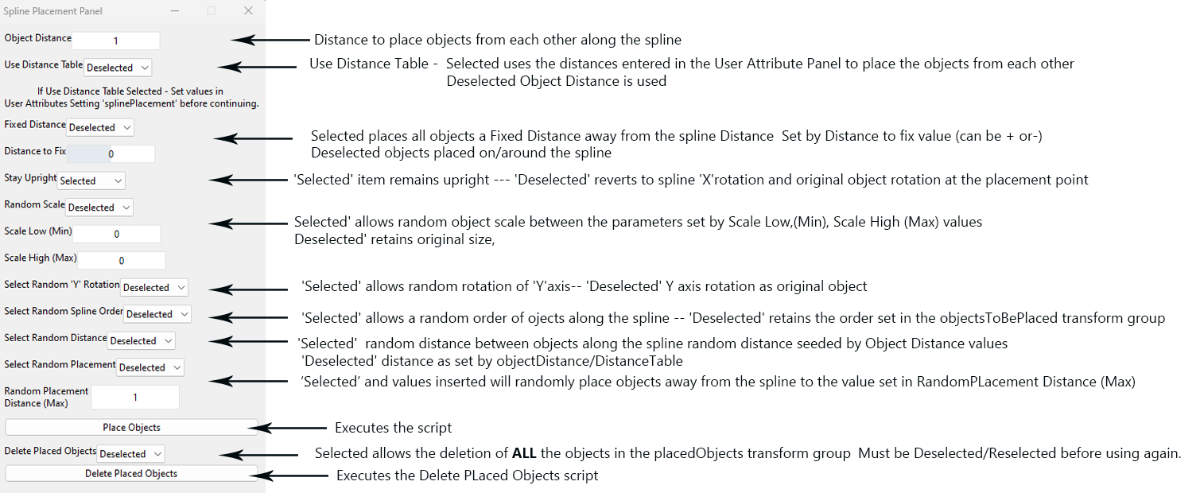
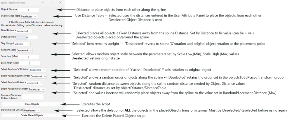
This is an updated version of the old spline placement script and uses a popup panel to input some permissions/values for the script to use its various functions. It combines the old splinePlacementTransform/splinePlacement/splinePlacement Delete scripts into one panel. Installation Download the Spline Placement Panel.zip (available at the end of this tutorial) , unzip and copy/paste the Spline Placement Panel.lua into the following directory, C:/Users/******/AppData/Local/GIANTS Editor 64bit 9.0.6/scripts or C:/Users/******/AppData/Local/GIANTS Editor 64bit 10.0.3/scripts Replacing ***** with your computer name. Using the script To activate in GE - Select Script -Spline Placement Panel a popup panel will appear on your screen, and a new transform group added to the Scenegraph also some User Attributes will be created in the User Attribute panel in GE, 9.0.6 the image below shows the first set up (1), second the User Attributes (2) finally the transform group with a spline created and placed in the correct position. In Giants Editor 10.0.3 the User Attributes panel is now in a separate tab in the Attributes Panel Panel All numerical inputs to the panel can be inputted either by slider or manually. To ensure correct values entered and avoid problems manual input is suggested. Values can be entered as a Float (e.g. 1.3) The objects will be placed at terrain height along the spline (using their individual point of origin location) from the 'S' cv to the ‘E’ cv and aligned to the to the spline along their "Z" axis (unless random location selected). For example a default primitive cube will be placed 0.5m below the terrain (point of origin in the centre of the 1m cube) e.g. if you have a hedge that is 4m long and 1m wide ensure the longest section (4m)is aligned to the 'Z' axis otherwise rotate it in GE until is aligned along the 'Z' axis and freeze transform rotation also ensure that the point of origin (where the gizmo shows when object is selected) is at the correct point The splinePlacement transform group must be selected in the Scenegraph for the script to work The panel image below gives basic information on the various settings followed by a more detailed explanation after. Object Distance This value is the fixed distance you want between the individual objects in the objectsToPlace transform group. Default is 1 but can be any positive value between 0 and 255 (inc Float values). It is also used as the first seed in the Random Distance (second seed being the Random Distance value) when Random Distance selected. Distance Table Unfortunately due to lack of UIString inputs in GE (only UIChoice/UIFloat/UIInt recognized) I have had to create User Attributes so that this function can be used. The Set Distance Table inputs for this option can be found in the User Attribute panel of GE when the splinePlacement transform group is selected Use Distance Table, ‘Selected’ uses the values in the Set Distance Table to set the object distance ‘Deselected’ uses distance value in Set Object Distance. Set Distance Table Sets a fixed distance between the objects in the objectsToPlace transform when Use Distance Table selected, number of settings must match number of items in the objectsToPlace transform and be separated by a comma. The first object in the objectsToPlace transform will always be put at the start of the spline (distance ‘0’), the entries in the Set Distance Table refer to the distance to the next object from the preceding one. So in the following example; A total of 3 objects in the objectsToPlace transform 1,2 and 3 Set Distance Table = 4,8,20 -- value in metres object ‘1’ placed at ‘0’ by default so no reference in distanceTable object ‘2 ‘ placed 4m from object ‘1’ object ‘3’ placed 8m from object ‘2’ object ‘1’ placed 20m from object ‘3’ object ‘2 ‘ placed 4m from previous object (‘1’ ) and so on until the end of the spline. A distance of ‘0’ will mean that two objects will be placed at the same location on the spline (e.g lamp post ,hedge ) Value entered can be a Float. Any incorrect entries in the Set Distance Table will result in a DISTANCE TABLE ERROR in the Console log. Random Scale/Random ‘Y’ Rotation/Random Spline Order/Random Placement can all be used in conjunction with the Use Distance Table. Note: if Random Spline Order used the set distances between objects will change according to the placement of the objects. Fixed Distance Selected places all objects a Fixed Distance away from the spline, Deselected objects placed along/around the spline Distance to Fix Value entered determines the the fixed distance away from the spline (can be + or -) StayUpright ‘Selected’ all objects placed upright ‘Deselected’ all objects aligned to original 'X,Y,Z' rotation Random Scale ‘Selected’ allows random object scale between the parameters set by the Scale Low, Scale High values. If an item is already scaled then it has to be freeze transformed (Scale) for this to work correctly, ‘Deselected' retains original size. Scale Low/ Scale High Value of the minimum and maximum Random Scale parameter, the value set applies to all scale axis (x, y, z) at the same time. Note: If Random Scale selected and Scale Low and Scale High values left at '0' zero you will get exactly that -- nothing !! Select Random ‘Y’ Rotation ‘Selected' objects randomly rotated on the 'Y'axis ‘Deselected' 'Y’ axis rotation follows the spline curvature ('X' axis) Select Random Spline Order ‘Selected’ allows a random order of objects in the objectsToPlace transform group along the spline. ‘Deselected’ retains the order set in the objectsToPlace transform group. Select Random Distance ‘Selected’ allows all the objects in the objectsToPlace TG to be placed at random distances along the spline. Random Distance seed set by Object Distance values. Select Random Placement ‘Selected’ the objects will be placed randomly around the spline depending on the values in the Random Placement Distance (Min) and Random Distance (Max). ‘Deselected ‘ objects in the objectsToPlace TG placed in order along the spline and at a distance set by ObjectDistance or Set Distance Table values. Random Placement Distance (Max) Objects will placed randomly either side of the spline to the max value entered. Place Objects Executes the script and places objects according to settings. Delete Placed Objects ‘Selected’ Enables the Delete Placed Objects section of the script To avoid inadvertently deleting wanted objects this selection must be Deselected/Reselected before being used again. Delete Placed Objects Executes the Delete Placed Objects section of the script 'Warning' this will delete ALL objects in the placedObjects transform The image below gives examples of some the basic settings The settings can be used in conjunction with each other for example Object Distance can be combined with Stay Upright/Random Scale/Random ‘Y’ Rotation/Random Spline Order/Random Distance/Random Placement. However when using the Use Distance Table only Random Scale/Random ‘Y’ Rotation/Random Spline Order/Random Placement can be used in conjunction with the Set Distance Table selection. Note: if Random Spline Order selected the set distances between objects will change according to the placement of the objects. When satisfied with the placement create a new suitably named transform group and copy/paste the complete placedObjects transform group into it, the objects in the original placedObjects transform can then be deleted using the Delete Placed Objects button or delete the complete splineObjects transform group if no longer needed. A new splineObjects transform group will be created each time the script is activated in GE - Scripts, however the splineObjects transform group once created can be used with different splines/objects/settings. To familiarise yourself with the new script, Open in a blank map and experiment with the settings and objects. If creating fences or power poles then the Fence/Power Placement script might be more flexible and suitable. https://farmerboysmodding.com/index.php?/topic/2452-fence-power-placement-script/ 1500z 20/1/2024 Script updated to cure DistanceTable Error when Use Distance Table deselected. splinePacementPanelCombined_25.zip
 1 point
 -
Version 08.12.23.01
1,328 downloads
Magnon Stone Picker BD Update Version 07.12.23.01 Per request by Truzedo I have made some changes to this mod. I usually don’t add huge capacity options, but I have had several requests and have seen many streamers with edited versions. So here you go. Major update I suggest selling your old one before adding this version. It should convert over, but you may lose material or get some initial warnings. There are 4 capacity and unload speed options, each option has to be selected independently in the store. I also added decal color selection and the ability to change material and color on the base and design parts. Materials are steel, chrome, stainless, brushed steel, plastic. Base Cost 132500 Capacity 50K - Free 100K – 2000 500K – 10000 1M – 70000 Discharge options free (when matched up correctly the unit will empty in around 10 seconds) 5K LPS 10K LPS 50K LPS 100K - LPS Update 03.11.23.01 Updated some modDescription to see if it helps with some server issues. Update 26.012.22.01 Lowered ground ref to help issues with pickup. This is the popular Magnon loading wagon with the windrowers converted into a stone picker. $132,500 50k/100k/250k capacity option Rim color, base and secondary/decal color option. Work speed of 15mph Huge thanks to grabbylatoosh and dogface for the testing and suggestions. magnonStoneField.mp4 magnonStoneShop.mp41 point -

Version 27.12.22.01
647 downloads
Updated version 27.12.22.01 Added the option to add/remove windrowers. Update version 29.01.22.01 Per a request by roar in my discord channel I added a buffer chamber to the baler so that now there is no need to stop you can just keep baling, depending on how much grass is on the ground it may slow down to match the timing of the chamber. This is the in game Impress 185 round baler wrapper with the added windrower arms and silage additive. Silage additive only works with grass it adds 5% yield. The speed is cranked up a bit, for a hired worker to work the best I suggest setting your cruise to around 13MPH if not the worker will not stop quick enough and leave product. Huge thanks to Grabby again for testing along the way. Also I would like to be sure to thank HungryCow Design for making the second windrow array image for me, without it I would not have been able to get effects to work on both sides. Another side note. This isn't my original idea. I found a wagon from FS15 that I believe dates back pre FS13 called the drake wagon. This loading wagon is based off that beast. 2022-12-27 10-08-08.mp41 point -
This plugin is for Blender version 3.0.0 and above. It allows the SplineCSV data created in the Spline CSV Creator script to be directly imported into Blender instead of having to use an earlier version of Blender and exporting/importing as an obj. NOTE: The latest version of the CSV script (available here https://farmerboysmodding.com/index.php?/topic/2495-fs-25-updated-scripts/ ) creates an .obj file of the spline in the CSVdata folder that can be directly imported into Blender without the need for any CSV conversion Installation Download the spline_csv_importer.zip file at the bottom of this topic. Open Blender (3.0.0 and above) Select –Edit—Preferences –Install and in the file browser navigate to where you saved the spline_csv_importer.zip file, Select and Install the Add-on. Once installed Activate it by selecting the check box (a single Left click usually brings up the Activation and Information panel) The Add-on can also be found in the Blender Preferences panel under Import-Export: Spline CSV Importer. To use the spline_csv_importer add on; Select File –Import – Import_Spline Data (*txt) A file Browser Panel will pop up, (an undocumented operator panel appear but this can be ignored it just means I haven’t documented it with Blender), Navigate to where your CSVdata folder has been created in your map root directory, double click to open the folder and select the required spline_Csvdata.txt file and select Import CSV . on the file browser. The spline_CSVdata will have been placed in a separate Collection named SplineCSV , retaining the original name,converted to an edge mesh and placed at the same location the spline in your map was, see image below for reference. All subsequent spline_CSVdata when added will be placed in this new Collection. Note: This Add-on will only create an single edge mesh (no other type of mesh) from a txt file created in the same format as the spline_CSVdata.txt file (i.e. no header), coordinates in the spline_CSVdata.tx have already been converted to the Blender format in the CSV Creator script and can be exported as an i3d or Nurbs curves (spline)directly back into Giants Editor. This new method will be placed in the relevant tutorial (along with a second copy of the spline_csv_importer.zip) https://farmerboysmodding.com/index.php?/topic/2413-export-a-spline-from-giants-editor-into-blender-to-create-roadsrailways-updated/ replacing the old method spline_csv_importer.zip1 point
-
i think i've now used most of the mods from this site and i have to say... they are incredibly under rated. they all offer some unique offering and they all help make playing FS19 a whole not more enjoyable. if you are new to this site or the mods, i strongly encourage anyone to take the time to download and try them out on your farming adventures. the tree maverick is exceptional 🙂 i wish the modders all the best and am always looking forward to new and exciting mods they release!1 point
-
Thanks to some sterling work behind the scenes by the Administrators it appears the log in problem I was experiencing is now solved so 'normal service' is resumed.0 points