Leaderboard


Popular Content
Showing content with the highest reputation since 06/18/2025 in all areas
-
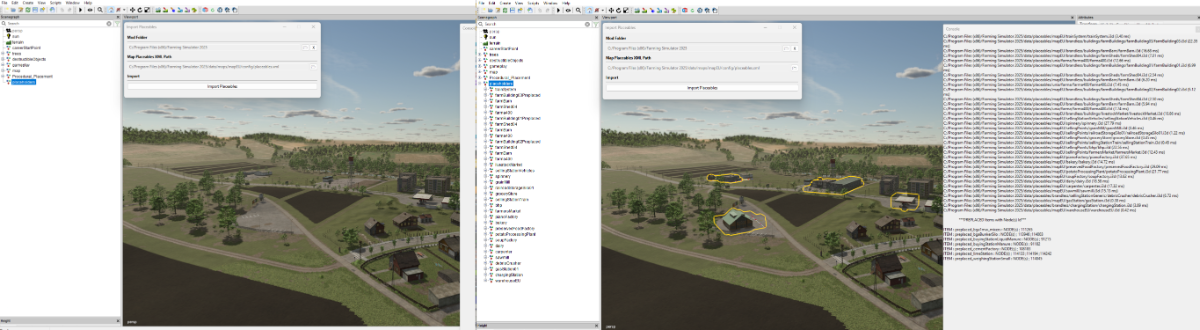
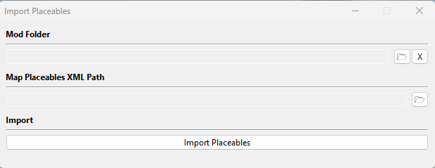
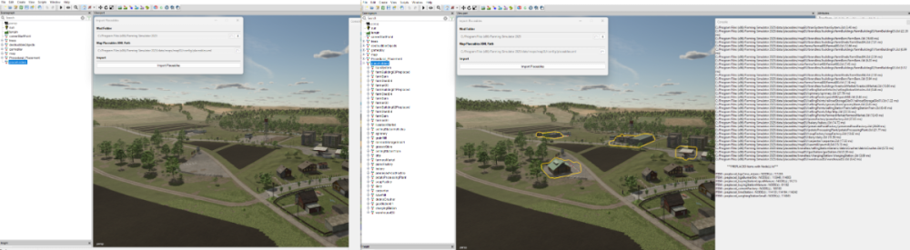
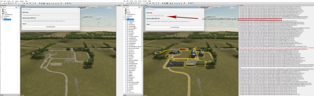
FS25 Import Placeables This is an updated version of the FS22 script which allowed the import into a map of all the placeable items in the placeables.xml (placeables.xml can be from a save game or another map) Original available here https://farmerboysmodding.com/index.php?/topic/2480-import-placeables/ With the changes made to placeables in FS25 the script will only import placeables that are not already in the map i.e. those who have not been preplaced using the placeables.xml <placeable isPreplaced="true" , any subsequent changes made to position/user attribute etc will still have to entered manually in the placeables.xml or by the Placeables Toolkit. However it will list all preplaced items in alphabetical order with their corresponding nodeId's for reference after the filepaths of the non preplaced items are printed in the console log. There are no requirements for setting any filepaths using the Script Editor. Installation and Use To use the script unzip the FS25_Import_Placeables.zip (available at the end of this tutorial) and copy/paste the folder to the location of your GIANTS Editor 64bit 10.0.4/scripts folder in this case it is, C:/Users/*****/AppData/Local/GIANTS Editor 64bit 10.0.4/scripts (replacing the *** with your computer name) Open GE and Select -- Scripts --FS25 Import Placeables When the script is first executed a check will be made to see if a 'placeholders' TG already exisits and if there is one or more instances of 'placeholders' TG's then a Warning will appear in the log with the duplicate 'placeholders' TG nodes for reference and investigation (if needed). A new placeholders TG will also have been created in the Scenegraph complete with the correct User Attributes (Placeholders.onCreate) With the Placeholders.onCreate added it will allow the placables to be seen in GE, the new placeable imports will be ignored when the map is opened in game and the placeables/preplaceables will be loaded as normal from the placeables.xml The script treats the preplaced placeables and normal placeables (those not preplaced and with a filename) in different ways. Normal placeables are loaded into placeholders TG in the Scenegraph and a print out of the file path to each one loaded will appear in the GE Console log. The name of each individual placeable in the Scenegraph will be its xml/i3d name not its placeable folder name. Preplaced placeables (if listed in the placeables.xml) are listed in the console log in alphabetical order together with their name and node Id's for reference (after the normal placeables filepaths). The following popup panel will also appear. Mod Folder Select the folder icon at the end of the Mod Folder line a file browser will appear navigate to where the folder containing any mods required by the map. For example if the map uses any external mods ( Required Mods ) in the normal My Games folder then the path would be :- C:/Users/****/Documents/My Games/FarmingSimulator2025/mods (obviously *** would be replaced by your computers name) Or if the mods folder is located elsewhere then something like this D:/Farming Simulator/FS25_mods Or if just importing from a map with no Required Mods D:/Farming Simulator/FS25_mods/FS25_SuperMap Basically the Mod Folder is the map/mods path where the placeables to be imported into the map are located. Note: All mods/maps must be unzipped for this to work correctly. Map Placeables XML Path Opening the file browser as before (selecting the relevant folder Icon) navigate to where the maps placeables.xml is located and select it. With the placeholders TG selected in the Scenegraph, select the Import Placeables button (move mouse away from the popup panel and wait for the Import Placeables button to turn back to white). The placeables will have been imported into the map at their relevant positions and a print out will appear in the consol log detailing the placeables file paths and also any preplaced placeables with their corresponding nodeId’s for reference. Some examples below the first using the default EU map (Zielonka) and the second using the Alma Missouri map EU map (Zielonka) Alma Missouri Limitations: Where fences/hedges/power lines have been created using the in game construction tool and then copy pasted into the placeables.xml from a save game these will not appear in their assigned position as any editing/deletion must be carried out in game and the placeables.xml manually adjusted from a new save game. The script relies on the placeables.xml being created correctly either by the Placeholders Toolkit or manually using the correct FS25 format (preplaced items must be created using the Placeables Toolkit to get the correct uniqueId) Script will only import placeables from i3ds so any placeables.xml script that does not have an i3dPath in its base.filename will not be loaded and an error message with the problem xml's filePath will be printed in the console log error message will also be printed if the mod directory doesn't have a mod associated with that map. The script will continue running until all placeables/preplaced types listed (including error messages) in the placeables.xml have been loaded It is possible to import all the placeables from one map into another (or even from a savegame) by opening the map in GE that is to receive the placeables and setting the Mod Folder to the donor maps filepath and Map Placeables XML Path to the donor maps placeables.xml then with the placeholders TG selected, select Import Placeables, placeables will be imported into the new map at their original positions. Placeables filepaths will still refer to the original map so adjustment will be needed if items kept. FS25 Import Placeables.zip
 1 point
 -
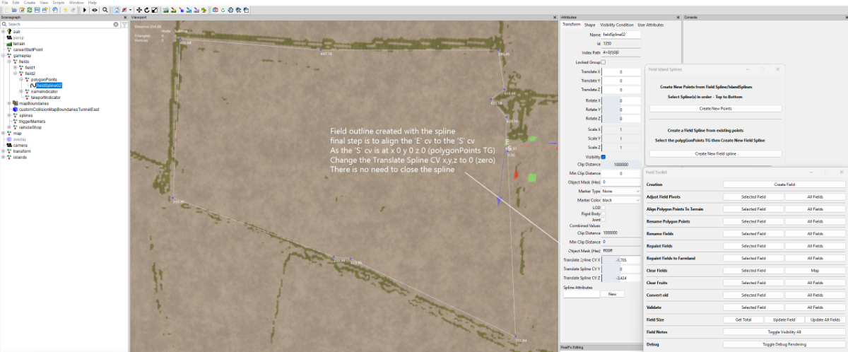
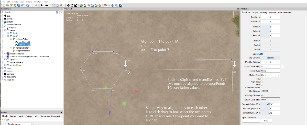
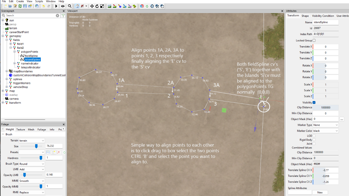
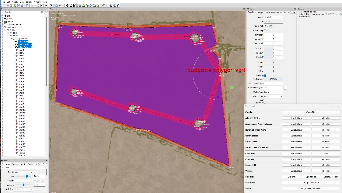
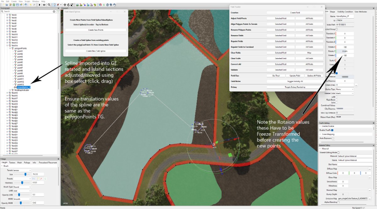
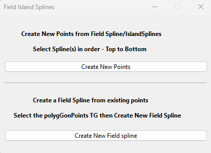
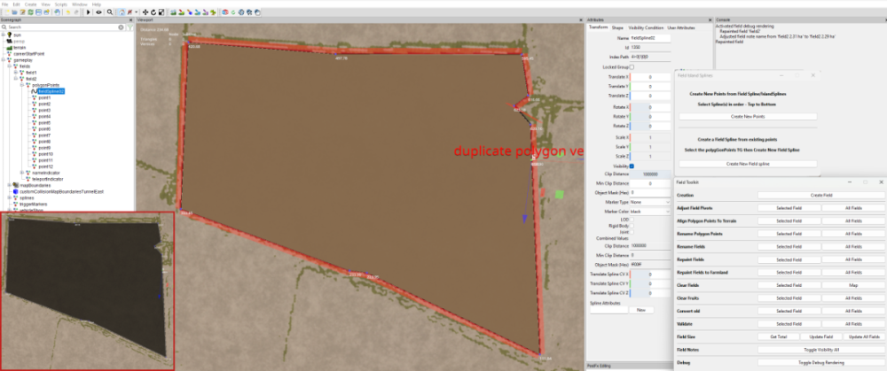
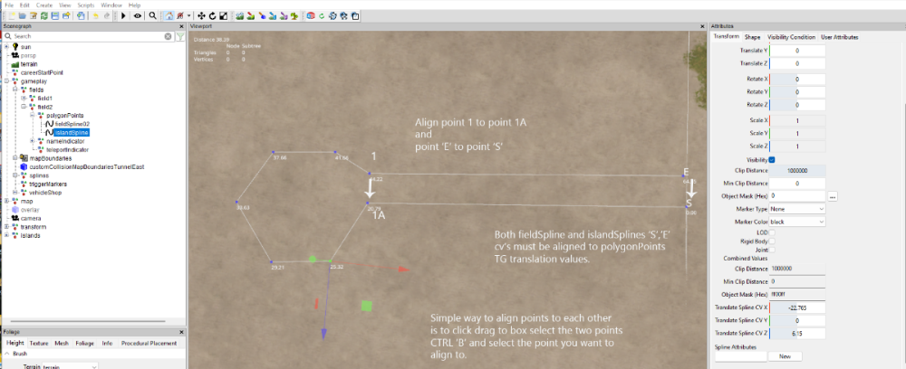
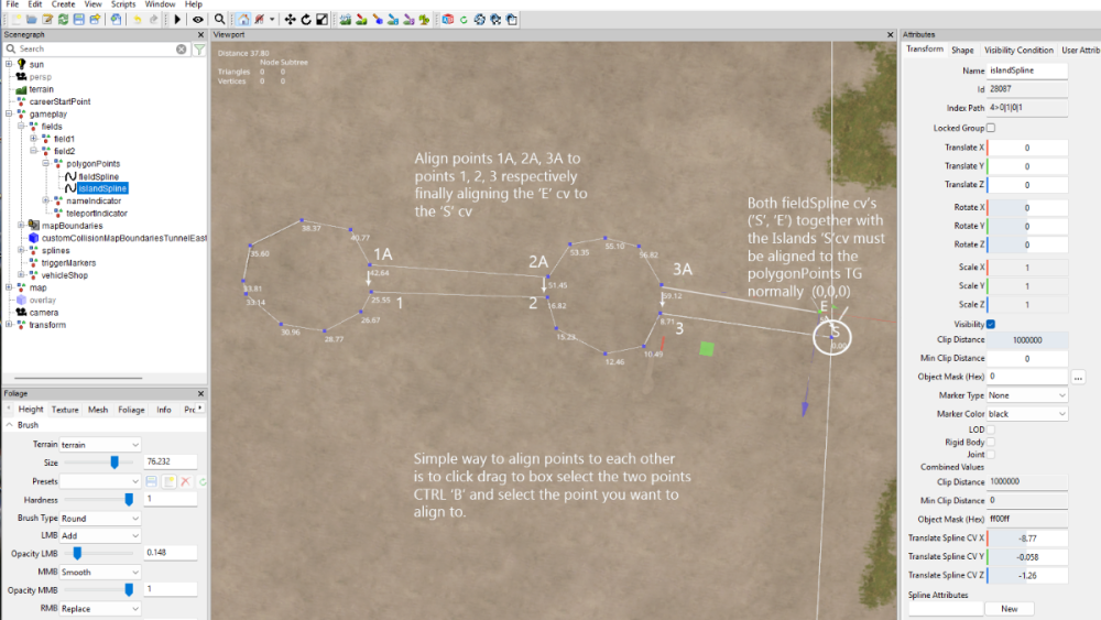
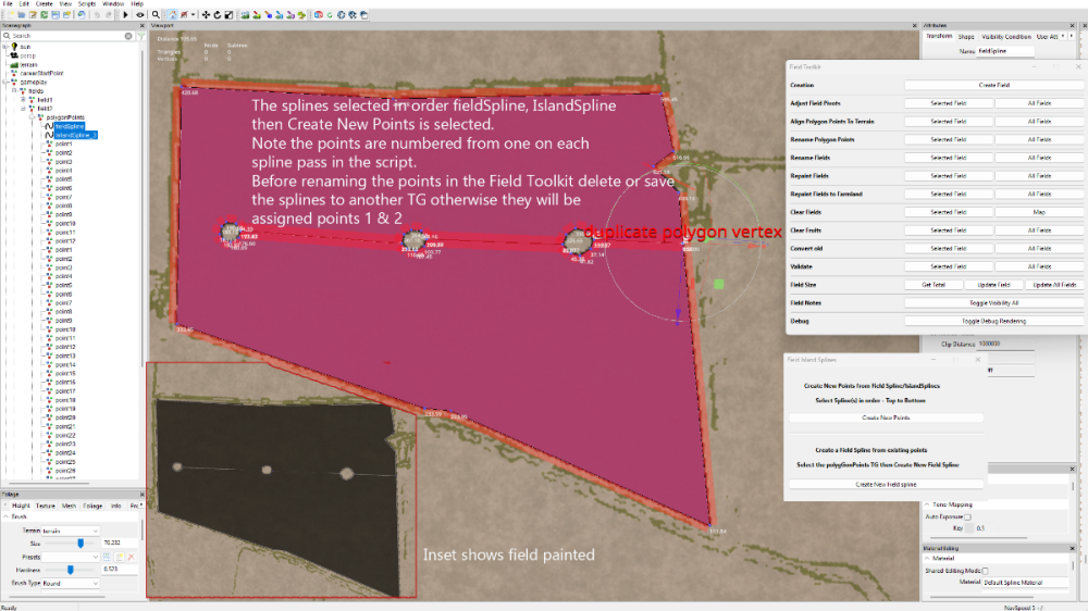
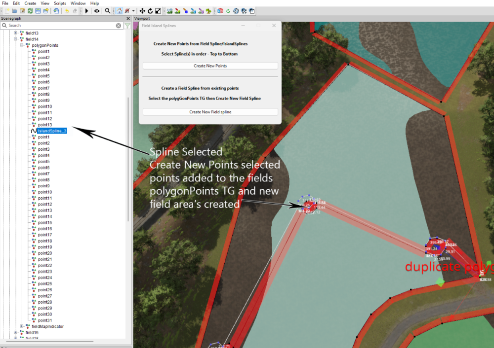
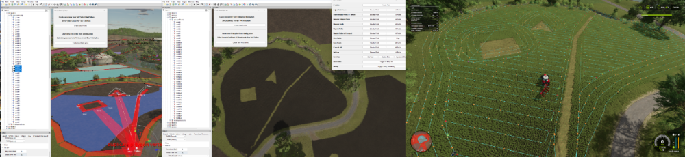
This tutorial will show how to create fields with/without islands using the Field-Island Splines script in conjunction with the GE Field Toolkit (Scripts –Shared Scripts– Map – Farmland Fields – Field Toolkit). Download the Field-Island Splines zip file (found at the bottom of this tutorial) and unzip, place the script in the following folder Download the Field-Island Splines zip file (found at the bottom of this tutorial) and unzip, place the script in the following folder C:/Users/******/AppData/Local/GIANTS Editor 64bit 10.0.4/scripts (replacing ****** with your computer name) Field-Island Splines script This script is in two sections the top panel section ‘Create new points from FieldSpline/IslandSplines’ is used for creating fields with or without islands it basically works by using a spline to create the field edge then using a second spline to create island shapes and when the Create New Points is selected it creates a new list of polygonPoints in the polygonPoints Transform Group. If creating a field with islands then the field and island splines must be selected in order, top to bottom, if only creating a field then just select the field and Create New Points, field creation can then be carried on using the GE Field Toolkit. The bottom panel section ‘Create new Field Spline from existing points’ is used when modifying existing fields, because of the different ways some fields are created (when adding Islands points placement accuracy is important) it may be necessary to create a new fieldSpline from the original polygonPoints . When Create New Field Spline is selected a new fieldSpline ( with the name of the current field ) will be created using the existing points and placed in the polygonPoints Transform group the original points can then be deleted. Because some base game mod maps fields do not close the spline correctly when the script is executed (Create New Field Spline) the script will automatically add a new final point at the same location as the ‘S’ cv, so effectively closing the spline. Islands can be created in any shape and once created saved in a separate folder so creating a ready made album of different shaped islands that can be used in any field. The following sections show how the script can used. Creating a Field with Islands from scratch When inserting points one quick method is to select CTRL ‘B’ and select the cv with the left mouse button, keeping the left mouse button pressed move to the next placement point and press Insert repeat until shape completed Open GE and select Scripts –Shared Scripts – Map – Farmland Fields – Field Toolkit to activate the Field Toolkit panel In the Scenegraph select the fields Transform Group (TG) (gameplay –fields), in the Field Toolkit pop up select Create Field a new field will be created in the fields TG (numbered in the next available value) in this case field2 (this is the field that will be created first in this tutorial), also in this TG is the polygonPoints,nameIndicator and teleportindicater transform groups. Selecting the fields2 TG , CTRL ‘B’ , left mouse click to place the fields2 TG at the entrance of your field ,the Field Notes panel will obscure the actual placement so in the Field Toolkit under Field Notes select Toggle Visibility All to turn it off. When placing fields it is best to place the field TG at the entrance to the field and move the fieldMapIndicator to the centre of the field if required and leave the teleportindicator at the field entrance Select the polygonPoints TG and delete all the points. In GE Select Create –Spline and cut/paste into the polygonPoints TG (do not middle mouse drag as it will assign new translations to the spline) name this spline fieldSpline02 (to avoid confusion when more than one spline is used) in the Attributes Panel -Shape Tab change the Spline Type to Linear this spline type is the same format used by the Field Toolkit when creating fields. Ensure you have the Translate Spline CV panels in the Attributes Transform Panel if not then Select – View – Show – Physics Selection – Enable All , the Translate Spline CV panels is required as some of the cv’s require accurate placement for the fields/islands to work correctly Select the ‘S’ cv and delete it -- This will align the start of the spline to the polygonPoints TG (0,0,0) Select the ‘E’ cv and working clockwise place the spline around the edge of the field (using the method described earlier) place the final point as close to the ‘S’ cv then in the Translate Spline CV panels set the X, Y, Z coordinates to 0 (zero) this will place the ‘E’ cv exactly on the ‘S’ cv (there is no need to close the spline), accurate placement is required otherwise problems will occur with the field generation. Field Spline If just creating a field then Select the spline – Select Scripts –User Scripts -Field-Island Splines and Select -Create New Points a new list of points will be created in the fields transform, delete or save the spline to another TG and carry on with the field creation using the Field Toolkit in the normal way. Image below shows the spline selected, script executed , Toggle Debug Rendering activated, Align polygonPoints to terrain (this also calculates the new field size) and the insets shows the field Repainted and the various log entries. Single / Multiple Islands Create a second spline cut/paste into the polygonPoints TG (immediately below the fieldSpline ) and rename it to islandSpline, (again in the Attributes Panel -Shape Tab change the Spline Type to Linear ) then delete the ‘S’cv as detailed above. With the ‘E’ cv selected draw out your shape (using the method described earlier) the images below show the creation of both single and multiple islands. Single Island Multiple Islands The following image shows a fieldSpline and a three island spline (islandSpline_3) being used to create a field with three islands (suitable for power/pylons installation) In the following image I have duplicated the islandSpline_3 and moved the islands individually to different parts of the field by box selecting (click drag) one of the islands and moving it by the translation gizmo ( if box select is used Ctrl ‘B’ will place all points at the same location) to a different position, then with the spline selected freeze transform any rotation value that has occurred during the island moving, repeating the method for the other islands before selecting Create New Points. The splines have to be moved (to another TG or deleted) before Aligning or Renaming the polygonPoints otherwise they will become point 1,2,3 respectively Then In the Field Toolkit panel Align Polygon Points to Terrain - Select – Selected Field Rename Polygon Points - Select – Selected Field Repaint Fields - Select – Selected Field Validate - Select – Selected Field Note: If you have a duplicate points warning in the console log then delete the duplicates and Rename Polygon points. Modifying Existing Fields For this part I will be using a US map created by the New Mod from Game option but the method should work with other maps, I will also be using the island_3 spline from the previous section. With the field TG (in this case field14) selected, in the Field Toolkit Panel- Select Clear Fields (Selected Field), Clear Fruits (Selected Field), this should clear any terrain detail paint and any crops associated with this field. With the island_3 spline imported into the map cut/pasted it into the polygonPoints TG and then adjusted by the box selecting (click drag) method to suit the proposed new layout Important, when adjusting the island sections ensure that they do not overlap or intersect with any other part of the spline otherwise problems will occur when the new field/island boundaries are created. The image below shows the initial creation of the new island’s layout, the spline was rotated to suit the new layout , this rotation must be Freeze Transformed –(Edit – Freeze Transformations –Rotate) ensure that only the Rotation box is ticked if the Translate box is ticked deselect it. Next with the spline selected, in the Field Island Splines panel select the Create New Points button this will create the new points from the spline and place them in the polygonPoints TG below the spline (Fig. 2) Fig.2 The final steps are as follows, Cut/Paste the spline into another place (TG) in the Scenegraph (otherwise it wil be renamed as a point and cause problems ingame) In the Field Toolkit panel Align Polygon Points to Terrain - Select – Selected Field Rename Polygon Points - Select – Selected Field Repaint Fields - Select – Selected Field Validate - Select – Selected Field Note: If you have a duplicate points warning in the console log then delete all of the named points and Rename Polygon points. Save the map and open in Game, below is an image of the farmlands panel and the islands with a Courseplay course confirming the new island layout. Field Island Splines.zip


 1 point
 -

Version 15.05.25.01
36 downloads
Auto fermenting silo. This silo is in the silo category, material is converted instantly, it is not a factory. This silo will automatically convert grass, hay, straw, chaff, and wood chips to silage. Cost 50,000 Capacity 10,000,0001 point