


WrinkleysRule
-
Posts
419 -
Joined
-
Last visited
-
Days Won
94
Content Type
Profiles
Gallery
Downloads
Events
Forums
Articles
Posts posted by WrinkleysRule
-
-
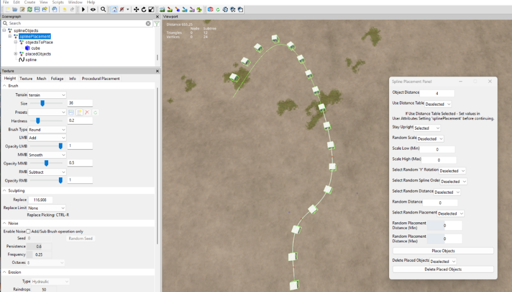
Primitive cube created
Spline added and adjusted
Script executed
placed cube and spline in correct position
Set distance 4
Selected Place objects
Simple as that
-
Example
-
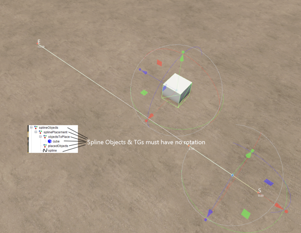
That is the correct script but when that script (splinePlacementPanelCombined_25) is first executed it automatically creates the transform groups required for operation the ones in your GE picture do not match those
Yours
Roads
|
splinePlacement
|
objectsToPlace
|
placedObjects
From the combined panel
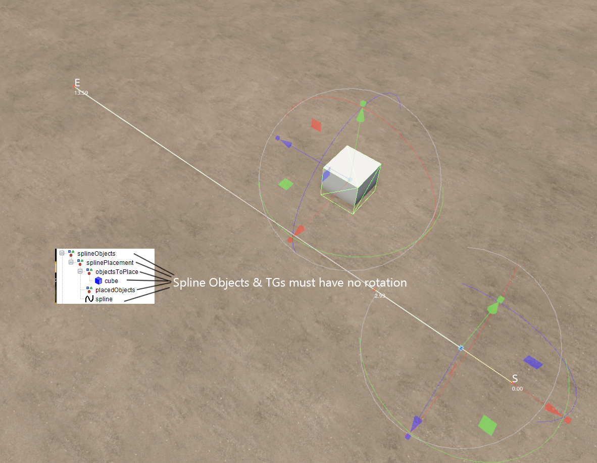
splineObjects
|
splinePlacement
|
objectsToPlace
|
placedObjects
So you are using a diiferent version of the script as I said in a previous post
Check your TG groups against the one shown in the image of my previous post
Also a pop up Panel with all the Settings/Inputs will also appear in GE
-
What script are you using as it doesn't appear to be the latest version (splinePlacementPanelCombined_25) of my scripts from your Transform Group Layout
Check your TG groups against the one shown in the image of my previous post
-
Check that the spline/objects and none of the TG's have any rotation if any found the items rotation must be freeze transformed.
-
Your object must be aligned along the 'Z' axis, rotate the object ine GE then freeze transform the rotation (and scale if changed)
From the tutorial ---https://farmerboysmodding.com/index.php?/topic/2414-terrain-height-paint-terrain-and-spline-placement-scripts-tutorials/ --- this uses the old method of user attributes but the settings remain the same
update Spline Panel Details here --https://farmerboysmodding.com/index.php?/topic/2469-spline-placement-combined-panel/
For best results, open any objects you intend to place in GE and adjust axis and origin accordingly, when done , freeze transform all scale/rotation settings (DO NOT freeze transform translations unless point of origin is relocated) on all the relevant objects.
example; if you have a hedge that is 4m long and 1m wide ensure the longest section (4m)is aligned to the 'Z' axis otherwise rotate it in GE until is aligned along the 'Z' axis and freeze transform rotation also ensure that the point of origin (where the gizmo shows when object is selected) is at the correct point
If you want to randomly rotate the objects then select Random 'Y' Rotation
-
Thank you.
Please bear in mind that the script is a simple as can be so some errors may occur if the TG groups are not formed in the way the script require.
-
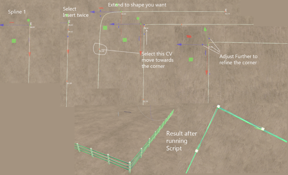
If your fence placement is so tight that you cannot move either the start or corner slightly (0.7m total in your case) for your 3m fence to fit (spline distance from start is now displayed at each CV) then you have two options,
carry on using multiple splines or create your own custom fence in Blender and export/import as i3d to Giants Editor.
-
Thanks to some sterling work behind the scenes by the Administrators it appears the log in problem I was experiencing is now solved so 'normal service' is resumed.
-
 1
1
-
-
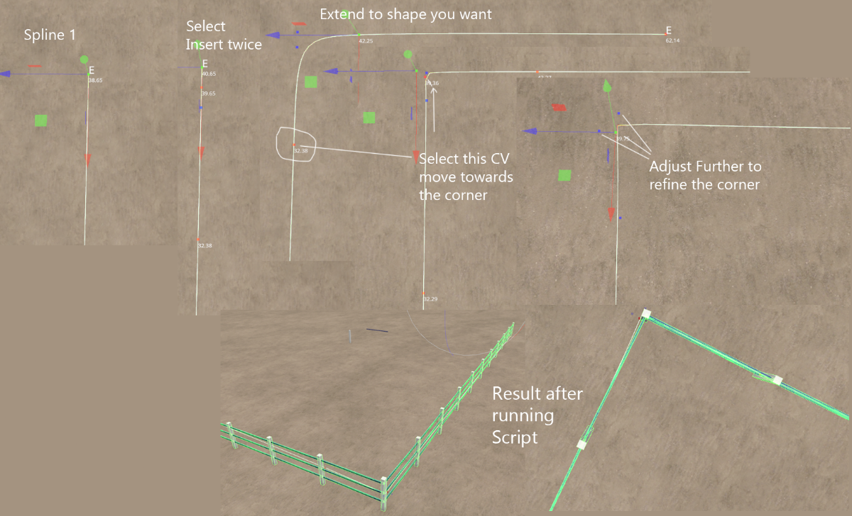
You have to adjust the points individually to get the sharpest corner the blue points do not have to be close to the corner they can be at different distances, the important one is the red cv point play around with the adjustments.
As you see by my example it is possible to get a 90 degree corner
here is an enlargment of the final positions
-
Attached is a simple script that will align trees to the terrain, place in
C:\Users\Your Computer Name\AppData\Local\GIANTS Editor 64bit 10.0.3\scripts
To use Select the Transform Group containing your trees and execute the script
LIMITATIONS The individual tree TG group must be formed as below i.e.
TG containing your Trees
|
pinusSylvestris_stage03
|
oak_stage03
etcAlso the script will only place the trees TG at the terrain height
if the trees LOD is set at a different height to its TG group the
script may not work as intended.
Obviously the trees point of origin must be at the base of the treeA print out of the number of trees parsed and the number changed will appear in the Console Log
-
 1
1
-
-
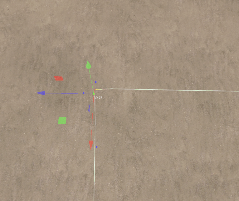
I have manged to sort of solve your 90 degree problem by creating a (almost 90 degree) corner with the spline the following image explains the method,
Note: The distance along the spline to the corner must be a multiple of your Set Post Distance, easy to see as the individual spline cv's now show the distance from the start of the spline.
-
@antler22 I will look into this 90 deg problem and see what can be done,
One question springs to mind, how are you creating a square spline ??
-
Quote
are there plans to do the create field & farmland scripts?
Not at the moment as I am still trying to workout how the new system works, apparently there are further updates from Giants in the pieline regarding this script
-
 1
1
-
-
I have now updated the following scripts for FS25 (zip file containing all scripts listed available at the bottom of this post)
To avoid confusion all future Updates to any of the scripts will require the complete FS 25 Script Versions.zip to be downloaded
Fence Power Placement --Updated 07/01/2025 Stay Upright Option removed fence/poles now automatically placed upright --15/06/25 Problem with upright position and placement when spline has a tight curve solved.
Paint Foliage by Spline Panel
Spline CSV Creator Panel - Updated 15/06/25 see changelog below
Spline Height Panel
Spline Paint Panel --- Updated 20/01/2025 Random value problem fixed and UI Changes -- see note in Spline Paint Panel below
Spline Placement Panel Combined --Updated 02/01/2025 Interim fix to first object placement problem --15/06/2025 Rotation/Placement problem fixed
Fence Power Placement
Fence Power PlacementScript updated to cure problem with pole's not remaining upright and pole placement not following spline correctly when spline has a tight curve, refer to tutorial for operation
Tutorial
https://farmerboysmodding.com/index.php?/topic/2452-fence-power-placement-script/
Spline CSV Creator Panel
Spline CSV Creator Panel OBJ_25 ChangeLog
Script operation is the same output has changed slightly
A new CSVSpline transform group is automatically created in the Scenegraph and the new CSV spline is created in this TG.
The new CSV spline ,spline.obj and csvData.txt are still added to the CSVData folder in the maps folder (same place as the map.i3d )which now hasPaint Foliage by Spline Panel
Operation of the script is still the same but the Panel Layout has changed.
Note: Random Foliage Paint will paint all states of a selected foliage.
Variable Foliage state When selected along with Random Foliage Paint option allows only the states
entered in Set Foliage State and Set Second Foliage State to be painted.
Random Foliage Distance seed can be adjusted by changing the Set Distance Between Foliage value
Spline Height Panel
Script just updated refer to tutorial for operation
Spline Paint Panel
Script just updated refer to tutorial for operation
For further information on the above scripts refer to the tutorial
Note: Random Width (Max) this is the max distance the texture will be painted either side of the spline (0 to Random Width (Max))
Random Distance (Max) this value is used by the RND function for the random distance the texture will be painted along the spline (0 to Random Distance (Max))
In both cases texture will be painted randomly at a distance between 0 and Random value entered at each point along the spline
Random distance bewteen textures can also be adjusted using the Set Texture Distance ValueSpline Placement Panel Combined
Script update with some Panel Layout changes and addition
Unfortunately the Use Distance Table values still have to be entered in the User Attributes panel. (now in seperate tab in the Attributes Panel)
I hope to combine them into the main panel at a later date.
Addition
Fixed Distance -- is the distance away from the spline (both + and -) you want the placement to start
(Look at it like a duplicate spline at the Fixed Distance value)
Changes
Select Random Spline Order – now uses the number of objects in the objectsTo Place TG as a random seed
If only one item in the objectsToPlace TG then I suggest adding a empty
TG to the objectsToPlace TG before selecting
Select Random Placement -- is the max distance around the spline (inc any Fixed Distance values)
Select Random Distance -- uses the Object Distance as seed to generate the random distance
If Use Distance Table Selected then Select Random Spline Order and Select Random Distance is disabled.See the tutorial for further information.
https://farmerboysmodding.com/index.php?/topic/2469-spline-placement-combined-panel/
There seems to be some confusion on where these scripts should be placed they should be placed here
C:/Users/*****/AppData/Local\GIANTS Editor 64bit 10.0.3/scripts -- replace ***** with your computers user name
not in the C:/Program Files/GIANTS Sosftware/GIANTS_Editor_10.0.3 folder as the scripts in this folder will be overwritten/updated when a new version is available.
To avoid confusion all future Updates to any of the scripts will require the complete FS 25 Script Versions.zip to be downloaded and unzipped replacing any existing scripts in the GE scripts folder.
-
6
-
7
-
-
Quote
which version of the Giants Blender exporter.
So which version ???????????
I haven't done any testing as yet (Latest Blender Exporter just released) but I don't think the latest exporter will be compatible with GE 8.2.2 you may need the earlier exporter available here
https://github.com/StjerneIdioten/I3D-Blender-Addon
https://github.com/StjerneIdioten/I3D-Blender-Addon/releases
However you will still be able to export from Blender as a .fbx file just means that you have to manually enter the texture details in the i3d using notepad ++
Regarding Blender I suggest you watch some of the Tutorials on youTube
From a previous post (above yours)
Here is one that just deals with adding materials
https://www.youtube.com/watch?v=MIVTzZKlmjE
For a better understanding then I suggest looking at the Blender tutorials at these two sites
https://www.youtube.com/@grabbitt/videos
https://www.youtube.com/user/AndrewPPrice
-
What version of Blender are you using and which version of the Giants Blender exporter.
Crossings/Junctions etc are created in Blender by adjusting/combining the mesh where two (or more splines meet) then exporting resultant as an i3d
-
I think you will find that the base maps pre-placed placeables (from the cofig/placeables xml) are already shown in the Giants editor if you use the Newmod From Game option.
For example search for preplaced_farmShedSmallOld and select it then check the User Attributes and it will give a list of attribues including AI splines/onCreate/uniqueId/xmlFilename
I don't know at the moment how FS25 deals with custom placeables, it may not need a custon script just adding the correct user attributes may work.
-
-
The scripts have been updated and are undergoing tests at the moment.
They will not be released until after the new game patch as things are likely to change not only in game but in GE so it would be pointless to release them at this time.
DEM's and Borders Tutorial
On the whole the same method can still be used however the dem size is now 2048 x 2048 16 bit greyscale.
If converting an existing 1024 x 1024 dem I suggest you select bilinear as the conversion this will minimise the 'steps', in my test case they appeared as shadows less than 0.2 m high.
I am working on a new tutorial for the Dems using Google Earth/QGIS to extract the dem from a SRTM/Lidar image and crop (to chosen area) and export it to a 2048x2048 16bit png which will be ready in due course.
-
1
-
-
PATIENCE IS A VIRTUE
-
Glad you have got it all sorted
-
If you use scripts from another site I suggest you contact the creator on that site as I cannot help you
I don't believe I have said I will post that script on this site (which appears to be an original TracMax script) any I have modified would be annotated as such) script on this site
I have given you a link to the correct zip file (which you appear to have downloaded)
Now I suggest you read the tutorial on how to use the scripts which can be found here
-
Quote
giant 9.0.6 splinePlacement_v1.3.lua from maxtrack
You should be using Version 1.5 (2022-06-18) which is available in the Updated Spline Scripts_18_12_2022.zip at the end of the tutorial.
Also the Spline PacementUser attributes will not appear until you select the splinePlacement transform group in the splineObjects transform group.

FS 25 Updated Scripts
in Mapping
Posted
Sorry never used spline street constructor so have no idea how it works I always create my roads using the CSV script and then importing the .obj of the spline created directly into Blender.