


WrinkleysRule
-
Posts
244 -
Joined
-
Last visited
-
Days Won
55
Content Type
Profiles
Gallery
Downloads
Events
Forums
Articles
Everything posted by WrinkleysRule
-
Answered query by PM but for anyone else with this problem all I can suggest is save your work and re boot Giants Editor. I have had this happen several times using the inbuilt scripts on the previous version of Giants Editor and it looks like it is also happening with this version.
-
What scripts are you trying to save as none of the scripts require saving before execution in the Script Editor in Giants Editor all are created and executed using User Attributes (Set up script) for Entry and selecting the main script for execution. For example with the CSV script Select ---Spline CSV Creator Set Up --User attributes created Enter your Map name Enter the distance you want between the cv's Select --- Spline CSV Creator script The script will have been executed the relevant folder placed in your map root folder.
-
I had no problems with laying crves before, all I am saying is that creating a spline layout just got more confusing, before it was just a case of selecting either end point ('S' or 'E') selecting Insert and Ctrl B to place the cv on the terrain at the point of your cursor, simple, now you have to be careful which end you start with otherwise you end up going backwards. One sorely needed function in the editor is to allow export of the spline as a nurbs curve (for use in 3d modelling software), something that has been asked for many times over the years along with updated instructions and tutorials.
-
Further info regarding splines. It would appear that selecting the 'E' end of the spline (which I thought denoted the End of the spline) and selecting INSERT on the keyboard the new cv is inserted BUT the gizmo does not move to the new cv setting but remains on the previous one requiring the down arrow to be selected before Ctrl B placing of the new cv If the down arrow is not selected before inserting anothe cv (on the 'E' endof the spline) the subsequent cv's will be placed back along the spline towards the 'S' cv However selecting the 'S' cv and selecting INSERT on the keyboard the new cv is inserted and the gizmo moves to the new cv location so not requiring the down arrow to be selected before Ctrl B placing I find it hard to see how this set up is an 'improvement'
-
After testing all the scripts it seems that they all still work with the new editor. However there is a new GUI set up for scripts in Giants Editor (user attributes no longer used for variables) so I will be updating all the scripts to use this new system along with some slight coding changes for better perfomance, You can check out the new GUI system by selecting Scripts --Terrain --Painy Terrain By Spline also the Giants Editor version of the Set Terrain Height by Spline now has a smoothing option. The new editor itself seems to be a lot better regarding terrain/ foliage painting with more masking options and less jagged edges. IMPORTANT: Make sure you update the game to 1.9.1 before using otherwise there will e some strange effects in Giants editor on all maps. Regarding the new spline adjustments in GE it appears that when you press Insert to create a new cv and then ctrl B to place it the previous cv is moved, at the moment to overcome this press Insert then down Arrow before ctrl B to place. There is possibly another method detailed but I can't seem to find it at the moment.
-
Create Field Dimensions and Farmland Tutorial
WrinkleysRule replied to WrinkleysRule's topic in Mapping
Paint Field Ground Foliage v2.1 script now updated to allow painting of Terrain Detail Angle and also Spray type. Script added to Paint Field Ground Foliage .zip and tutorial update to reflect changes -
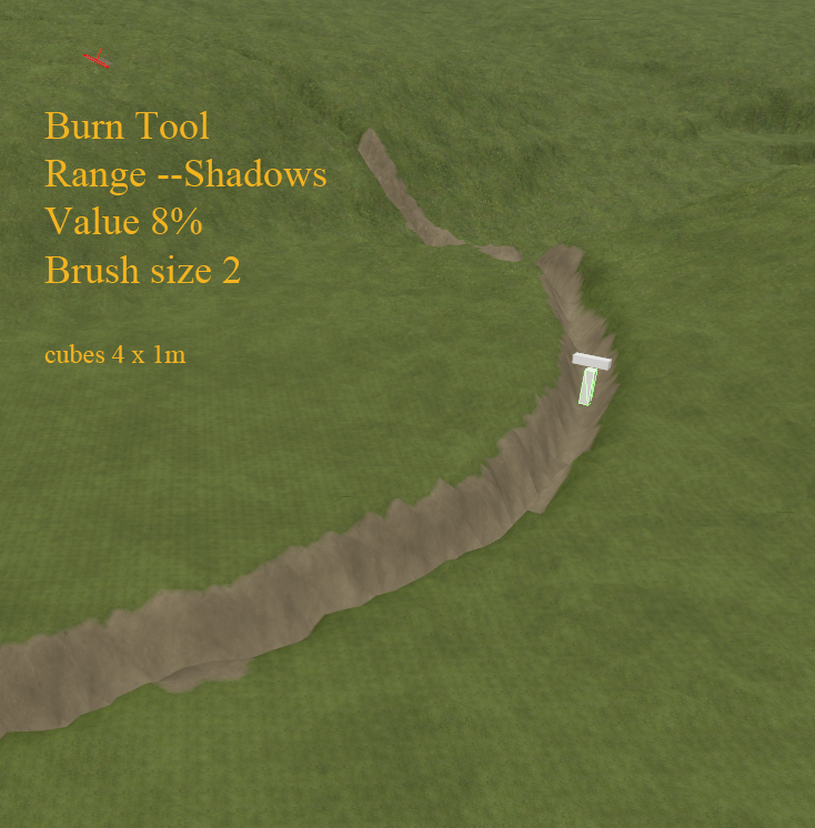
I am a bit confused as to what you are trying to achieve by splitting up the dem, by using different image editors you are creating interpolation problems, "I use Paint.Net because I'm comfortable with the tools in it but I don't use it to save anything" "I put this into GIMP as another layer " --- So the paint net image as well as being adjusted (in paint.net) must have been saved to enable it to be pasted as a separate layer in Gimp "Now I got the idea of going back to add "detail" to the fields with some erosion, washouts, etc. " The above quote sugggests you are tring to create ditches and low area's caused by rain, which is easily created in GE without the need for splitting or changing a dem in another programme ( incidentally you haven't mentioned how you get just the fields using the field dimensions, I take it that is a separate script in GE) There are three easy methods to create rivers/streams/ditches and any form of erosion 1. Freehand in GE using the available tools https://gdn.giants-software.com/videoTutorials2.php?s=7&p=0&c=4&LANGUAGE=en https://gdn.giants-software.com/videoTutorials2.php?s=7&p=0&c=5&LANGUAGE=en 2. Using the spline Height script see tutorial link below 3. In PhotoShop or Gimp using the Burn tool Open Dem in the image editor (backup first) and set the Burn tool brush Range Shadows value 8% (higher values deeper cut) brush size 2 (2 pixels will give a 4m wide stream) brush hardness can be adjusted for the sides a hard brush will give steep sides a soft brush will give more rounded edges Now just draw your river/stream etc directly on the dem at your chosen position (using a pda overlay if necessary, map image only not including border area) and save/export to the map data folder,do not close the image editor because by using the undo function in the image editor you can easily redo you settings to get the desired effect. The same method can also be used for erosion of a particluar area example image Another link you might find useful This is a link to a totally free legacy edition of PhotoShop (CS2) that I use and find it more than adequate for editing all the textures in FS19 (with the Nvidia dds plugin ) https://www.techspot.com/downloads/3689-adobe-photoshop-cs2.html
-
Couple of questions firsts what was the other programme you used to alter the dem and what was the settings you used to save it and secondly why did you need to use another programme when there are erosion tools (both hydraulic and Thermal) in GE. What do you mean by " import only the field areas of the DEM " because adding a new section to any dem will only lead to problems, bear in mind each pixel is equivalent to 2 sq metres (1024 x 1024 dem) Paint. net is not recommended for any png files as it only saves in indexed colour not greyscale so any file saved would have to be resaved in Gimp or Photoshop leading to more distortion due to multiple pixel changes. from the tutorial "Image editor (Photoshop, Gimp etc) --- Paint.net not recommended as it doesn't appear to save in 8bit greyscale format only index colour" One further thought are you testing the new altered dem in GE or ingame from a saved game.
-
Create Field Dimensions and Farmland Tutorial
WrinkleysRule replied to WrinkleysRule's topic in Mapping
New script added Paint Field Ground Foliage and new section Painting Field Ground Type and Foliage added to the tutorial. This new scripts allows the Terrain Detail Ground Type (i.e. Plowed,Cultivated etc) and also a chosen foliage/ foliage state i.e wheat, harvest ready) to be painted using the field transform group (i.e. field01) Currently the Terrain Detail Ground Type (i.e. Plowed,Cultivated etc) will only be painted at the default angle and Spray Type is also not available these options will be addded on a future update to this particular script. -
This is an updated standalone version of the original script by Stegei (Giants CEO) that prints the Layer Data to a text file (Layer_Data.txt) in the map root folder Handy easy reference for scripts that require texture layer data such as the FoliageCreator script (https://ls-modcompany.com/forum/thread/6525-fs19-ge-script-foliagecreator/) and the Terrain Paint R scripts ( Installation Unzip the file and copy paste the contents into C:/Users/Your Computer Name/AppData/Local/GIANTS Editor 64bit 9.0.3/scripts folder To use, Open map in Giants Editor , open Script Editor (Wnidow-Script Editor) and select the Terrain Layers 2 script and insert your map name and execute A print out of your Terrain Texture layer details will appear in the GE console window and a Layer_Data.txt file with this data will be created in the map root folder Terrain Layers 2.zip
-
Create Field Dimensions and Farmland Tutorial
WrinkleysRule replied to WrinkleysRule's topic in Mapping
Correct version of the tutorial now posted -
Create Field Dimensions and Farmland Tutorial
WrinkleysRule replied to WrinkleysRule's topic in Mapping
Please note the Create Field Dimension script is still under development so changes will ocuur in later updates, mainly to the parrellogram section of the script to try and reduce the current number of corners. -
Create Field Dimensions and Farmlands Tutorial This tutorial will endeavour to show you how to create field dimensions, paint the farmland area (InfoLayer_farmlands.grle) and automatically add the relevant farmland entries in the farmland.xml together with painting your chosen Ground Type (i.e Plowed,Cultivated etc) and painting foliage at a chosen growing state on the chosen field using custom scripts. For clarity the abbreviation TG will be used to denote a Transform Group throughout this tutorial. I would like to thank Modelleicher for allowing me to use and giving permission to slightly modify the following scripts in this tutorial in order to add some extra functions. Create Field Dimension Panel Creates field dimensions from markers Paint_Farmland_Field_ID_Panel Paints the InfoLayer farmlands.grle and adds relevant data to the farmlands.xml. Paint Field Ground Foliage Panel Paints the chosen Ground Type (i.e.Plowed,Cultivated etc) and Foliage at a chosen state (i.e. wheat, harvest ready). All scripts are available in the Field Dimensions and Farmlands zip file available at the end of the tutorial. Also have a look at the following youTube videos by Modelleicher on the creation of the original scripts and for a master class on script creation. https://www.youtube.com/watch?v=jLL7x064mJc --Field Dimensions https://www.youtube.com/watch?v=QhCOBkOxjPE –Paint Farmlands https://www.youtube.com/watch?v=dxnZI8C02NY --Farmlands.xml Create Field Dimensions, Create Farmlands and Paint Ground and Foliage on the field The three scripts used for this are the Create Field Dimension Panel, Create Farmlands Panel and the Paint Field Ground Foliage Panel. The Paint Field Ground Foliage Panel script now automatically reads the Foliage Type, Ground Type, Ground Angle, Spray Type associated with your map from the map.i3d and displays it in a dropdown selection. However the Foliage State for each Foliage Type still requires a number value (position in the Layer State dropdown in GE) To assist with this the script now reads all the Foliage States of each Foliage Type directly from the maps foliage folder xml’s and prints result to the console log and to a foliage_States.txt file in the same folder as the map.i3d for easy reference, the image below shows the extracts from console log print out and the foliage_States.txt file . The foliage states listed here are from a test map based on the US map so yours may differ depending on your map set up. Open your map in Giants Editor and Select –Scripts, select the Field Dimensions and Farmlands folder to open it and then select the Create Field Dimension Panel script a popup Panel will appear on your screen. A new transform Group will automatically have been created in the Scenegraph called Field_Creation_Transform consisting of the following TG groups newFieldMarkers – this TG will be the the reference point for the fieldMapIndicator and also contains the Markers transform where the markers are placed. fieldsNew -- containing a fields transform although this will have the FieldUtil.onCreate attribute set by the script I suggest deleting the attributes and reassigning them by Add New Attribute --Type --scriptcallback -- onCreate -- Add and in the new onCreate box enter FieldUtil.onCreate as some times GE doesn't recognise some script set User Attributes. This only applies to the field TG in the fieldsNew TG. The relevant entries created in this fields TG must be copy/pasted in to the gameplay –fields TG replacing originals before using in game farmlandDimensions -- containing a fields TG with the FieldUtil.onCreate attribute set. This will be used in the creation of the farmlandsDimensions Create a primitive (Create –Primitives, I will be using a cone throughout this tutorial.) and cut/paste into the newFieldMarkers transform (this will be the position of your fieldMapIndicator in the new fields TG). Copy/paste a cone into the Markers TG Your Scenegraph should now look like this. If you haven’t already got an outline of your proposed field area then I suggest you make one using the Terrain Detail Texture Mode and a suitable texture. Once you have a field border then CTRL ‘B’ the newFieldMarkers transform into the field area. Note: The newFieldMarkers transform MUST be placed in a position that allows ALL the field boundary to be seen from that position (the cone in the newFieldMarkers TG will provide a reference point) otherwise the script will not work correctly, so for complicated field shapes you will have to create the fieldDimensions manually or by using FieldDimensionsWithBitmap script available from here https://ls-modcompany.com/forum/thread/5852-fs19-ge-script-fielddimensions-per-bitmap/ Also the Markers (cones) must be in a consecutive order, so if you have to add any additional markers to your layout (after creating one) then the extra marker must be placed in between existing ones in the Markers TG as the script uses each marker in turn to create the field Dimensions. Place the ‘cones’ along the edge of the field by CTRL ‘D’ (copy existing cone)-CTRL ‘B’ (place new cone) at suitable points as shown in the following image ( I have scaled the cones up for better definition). Using the fields transform in the fieldsNew TG to create the new field dimensions. In the Enter Field Number box enter the field number you want for this field. Now, first selecting the fields transform and holding Ctrl key select the Markers transform, releasing the Ctrl key and select the Create Field Dimension button. The new field dimensions together with the fieldMapIndicator will be created in the fields TG in the fieldsNew TG, if they are not visible in GE then with the fields TG selected Select – Scripts – Map –Toggle Render Field Areas and they should appear in GE. A Created Field Dimension for Field ‘field01’ message will also appear in the console log (field number will change to field created in subsequent operations). Results shown in following image. The script sets the default for fieldGrassMissions and fieldMissionAllowed to false. To change this to your prefered setting select the field number transform (field01 in the folowing image) And select the relevant box as shown below. fieldAngle can be left at 0, fieldDimensionIindex and nameIndicatorIndex refers to their position in the field(01) transform group 0 and 1 respectively. Painting the Field and adding details to farmlands.xml There are some tasks and settings to be done before this can be carried out. Firstly if you are starting from scratch then I suggest you ’Wipe’ the infoLayer_farmlands.grle if you already have fields painted then skip this next step. ‘Wipe’ infoLayer_farmlands.xml In GE zoom out until the whole map area (I use a pda camera for this ) is in view select the Terrain info Layer Paint Mode and in the Info Layer Painting panel select farmland in the drop down, select all the info channels (1-7). In the Terrain Editing Brush panel set a radius of 1000 and Brush Type square, paint the whole map area (ensure it is completely covered otherwise you will get errors in the log) and save the map. farmlands.xml If you have renamed your farmlands .xml then obviously use that name in the following and check the note in the Create Farmlands section regarding filePaths. Navigate to where the map.xml is located in your map normally Map Name/maps/mapUS (orFR/alpine) And open this in notepad++ and locate the <farmlands filename entry in this case it is <farmlands filename="$data/maps/mapUS/farmlands.xml" /> Change this to <farmlands filename="maps/mapUS/farmlands.xml" /> if you want to keep your farmlands.xml in the default position However I am going to put my farmlands.xml in a separate xml folder so my <farmlands filename entry will look like this <farmlands filename="maps/mapUS/xml/farmlands.xml" /> with the farmlands.xml placed in the new xml folder. Save the maps.xml. Open the farmlands.xml in notepad++ and ensure the path to the infoLayer_farmland.grle is correct the densityMapFilename should read densityMapFilename="maps/mapUS/data/infoLayer_farmland.grle" If you are starting from scratch open farmlands.xml and delete all the farmland entries like so. However if you already have fields created in the farmlands.xml then only delete any entries that have not yet been created leaving only the created ones e.g A second set of field Dimensions now need to be created in the fieldDimensions TG using the original set of markers. Select each of the field border markers in turn and move them to the outside of the field boundary (or if you have two fields that you want to have as one farmalnd area, to the outside of the whole area) Remember if you add any new markers the extra marker must be placed in between existing ones in the Markers TG as the script uses each marker in turn to create the field Dimensions. Once done first select the fields transform in the fieldDimensions TG and holding the Ctrl key select the Markers TG release the Ctrl key and select the Create Field Dimension button. Note: the field number is left as 1 in the Create Field Dimension script because this is the field number to be painted. Create Farmlands To paint the field infoLayer_farmland_grle and create the correct entries in the farmlands.xml in Giants Editor Select –Scripts, select the Field Dimensions and Farmlands folder to open it and then select the Create Farmlands Panel script, a popup Panel will appear on your screen. Set Land Price Scale- Enter your chosen price scale multiplier default is 1 Set NPC Area- Enter your chosen NPC area "ALPINE", "US" or "FR" Number of Different NPC’s Number of different NPC's (found in base maps npc.xml normally default 15) The npc number is randomly selected between 1 and the npcCount value in the script. Show on Farmlands Screen Default is true --false will stop field being shown on farmlands screen i.e showOnFarmlandsScreen="false" /> <!-- BGA, farmland bought via placeable --> When true the game scripts automatically show the farmlands so no showOnFarmlandsScreen entry will appear in the farmlands.xml Default Farm Property Default is false --true assigns ownership of field to player farm i.e defaultFarmProperty="true" /> Once you have made the relevant settings in the Panel , with the field01 TG (farmlandDimensions – fields - field01) selected, select the Create Farmlands button. Note: If your map has a non standard heiarchy or extra custom NPC characters then you will need to adjust some variables in the script, obviously if the map is a standard layout then this section can be ignored. The variables to change are, local farmLPath = {"farmlands.xml","xml/farmlands.xml"} – these are the normal places where the farmlands.xml is found. The script will automatically search for the xml in the following locations Main map folder Main Map/maps folder Main Map/maps/mapUS (orAlpine,FR) folder If your farmlands.xml has another name or placed in a different folder location then add this to the ‘farmLPath array ‘ not forgetting the quotes. local areas ={"ALPINE","US","FR"} – If you have another set of custom characters at a different location then add this to the ‘areas’ array again not forgetting the quotes. local npcCount = 15 -- If you have more custom characters then increase this number to the new amount. To carry out any of the above changes open the script in the GE Script Editor Window – Script Editor -- Field Dimensions and Farmlands - Create Farmlands Panel At the top of the script (lines 12,13,14) you will find these variables, adjust as necessary and save the script. The Script Editor can now be closed as it is no longer needed and the script is ready for use. The image below shows the resultant farmland painted (in Brown) with the farmlandDimensions overlayed in green. The inset shows the same farmland but selecting Farmland 1 in the Lands dropdown and show unmasked selected (removes the background colour) A INFO : Farmland id 1 Painted and farmlands.xml entry created message will also appear in the console log (field Id will change to any new Id created for subsequent fields). Note: Colours will vary as the Toggle Render Field Areas script randomly assigns colours to fields And the new entry in the farmlands.xml showing field 1 as belonging to the farm. You can create the fields in any order the script will adjust the farmlands.xml numerical order automaticaly and insert the next number in the appropriate place replacing the <farmland/> with the new field entry as shown below. If you try to create/paint a field ID that already exists then a warning will appear in the Console panel window and the existing farmland ID will not be overwritten , for example, +++++++++++++++++++++++++ Farmland ID 25 already exists in farmlands.xml Delete farmland Id 25 in the farmlands.xml if you wish to create a new farmland at Id 25 +++++++++++++++++++++++++ Should you wish to increase/decrease the size of the painted farmland area then in GE with the Terrain Layer Info Paint Mode selected and the farmland selected in the drop down in the Info Layer Painting Panel With the cursor over the area you wish to change select Ctrl ‘R’ on the keyboard and the correct farmland entry will appear in the Info Layer Painting Panel ready for you to paint Once happy save the map (sets the infolayer_farmland.grle) Painting Field Ground Type and Foliage This requires the Paint Field Ground Foliage Panel script. The script requires the correct Farming Simulator 2022 installation path, it uses a default path of "C:/Program Files (x86)/Farming Simulator 2022/". If your installation path is different then open the script in the GE Script Editor Window – Script Editor -- Field Dimensions and Farmlands - Paint Field Ground Foliage Panel At the top of the script at line 24 there is the following local gInst = "C:/Program Files (x86)/Farming Simulator 2022/" replace the "C:/Program Files (x86)/Farming Simulator 2022/" with your file path (including the quotes) and save the script. The Script Editor can now be closed as it is no longer needed and the script is ready for use. This script uses the created field dimensions to allow the painting of the Ground Type and Foliage to the field dimension area With the map open in GE select Scripts select the Field Dimensions and Farmlands folder then the Paint Field Ground Foliage Panel script the following pop up panel will appear on your screen Set Foliage Layer Select the Set Foliage Layer box and a dropdown will open listing all the various foliage layers in your map for example 'terrainDetail' Set Foliage State Only applies if terrainDetail not selected in the Set Foliage Layer. The number entered corresponds to the position of your chosen foliage state in the Layer State dropdown in the Foliage Layer Painting Panel of GE. To assist with finding the relevant foliage state all the foliage states for each ‘crop’ are printed in the console log and also in a foliage_states.txt file in the map.i3d folder Ground Type Selected from the Ground Type dropdown (all available terrain detail ground type’s listed). Ground Angle-Degrees Selected from the Ground Angle-Degrees dropdown (all available ground angles listed). Spray Types Selected from the Spray Type dropdown (all available spray types listed) Paint Ground/Foliage Executes the script Once you have entered your chosen settings with the field TG (i.e. field01) selected, select the Paint Ground/Foliage button Note: the Spray type works the same as if painted in GE so you will still get the requires lime/etc in the in game field info gui. The images below show console log print out for foliage states and the Paint Field Ground Foliage Panel settings for, Set Foliage Layer --terrain detail, Ground Type Ridge, Ground Angle -90,Spray Type Manure. Set Foliage Layer- potato, Foliage State - 5 (green big) Ground Type/GroundAngle/Spray Type left as previous as they have no effect if terrainDetail not selected. To erase/change any option select the foliage layer you want to change and either deselect it (blank) to remove or choose another foliage type , the same applies to the other options. For example selecting terraindetail and deselecting (blank) in the other setting(s) to be erased and selecting the Paint Ground/Foliage button will revert the field to the original ground texture ( in this case ‘dirt’) To remove foliage , select that foliage in the Set Foliage Layer dropdown and enter ‘0’ in the Foliage State select the Paint Ground/Foliage button will remove all the foliage of that selected Foliage Layer The script will work on any TG that has field dimensions so for example can be used to fill a predefined area that has been created using the field dimensions script. Note : Density Map Modifier details will also be printed in the log whenever the Paint Ground/Foliage script is used, this is not an script error but a GE info regarding number of channels e.g. DensityMapModifier: defaulting num channels to 10 DensityMapModifier: called from =C:/Users/Admin/AppData/Local/GIANTS Editor 64bit 9.0.6/scripts/PanelScripts/Field Creation Scripts/Paint Field Ground Foliage V4.lua (275) If manually painting the terrain detail a little tip, in the Limit to Texture drop down in the Foliage Layer Painting panel select the texture of your field area this will restrict the painting to that texture only and not paint over the grass border texture the image below shows the effect of these settings. To create other fields repeat the above methods. Once you have completed all your fields then, if starting from scratch cut/paste the fields TG from the fieldsNewTG to the gameplay TG replacing original. However if you already have fields created then copy/paste the fields TG from the fieldsNewTG to the gameplay TG and move any existing fields into the new field TG. Save the map. --------------------------------------------------------------------------------------------------------------- Method 2 Using a Spline This method is more or less the same as the first except I will be using a spline to create the field border and place the markers, the placedObjects TG will be used instead of the Markers TG when creating the field Dimensions. The scripts used in this section of the tutorial are:- Spline Placement set –Transform/Place/Delete Sets the required transform groups in the scenegraph Places objects along a spline Option to delete the current placed objects Create Field Dimension Panel Creates field dimensions from markers Create Farmlands Panel Paints the InfoLayer farmlands.grle and adds relevant data to the farmlands.xml. Paint Field Ground Foliage Panel Paints the chosen Ground Type (i.e.Plowed,Cultivated etc) and Foliage at a chosen state (i.e. wheat, harvest ready). Spline Paint Panel Paints chosen texture(s) along/either side of a spline If you haven’t used the Spline Placement scripts/ Spline Paint Panel scripts before then I suggest you have a look at the tutorials linked below. https://farmerboysmodding.com/index.php?/topic/2414-terrain-height-paint-terrain-and-spline-placement-scripts-tutorials/ Initial set up When using scripts in GE that do not require access to the script editor (such as the Toggle Render Field Areas) what I normally do is go to Scripts –Map, which opens the folder at the bottom of the popout is Detach Menu, selecting this undocks the folder from the Scripts list which can then be place anywhere on the screen or redocked into the side panels (see images in the tutorial for examples). Open map in GE, open Script Editor (Window – Script Editor) select and execute the following script (found in the Spline Placement folder):- SplinePlacement Transform – this will create the necessary transform group heirachy for the script In GE create a spline (Create—Spline) and cut paste it into the splinePlacement transform. Create a primitive (Create—Primitives) again I will be using a cone, and copy/paste one into the objectsTo Place transform and another into the splineObjects transform (this one is used as a guide for the fieldMapIndicator) . I will be using the exsisting transform group farmlandDimensions TG from the previous method infoLayer_farmlands.grle and farmlands.xml set up is the same as previous method. The splineObjects transform will be used to create a field boundary and place the markers, the spline itself will also be used to paint a field border in a suitable texture The farmlandDimensions TG with the fields transform will be used to create a second set of fieldDimensions in a new (in this case ) field02 transform to be used for painting the infoLayer_farmland.grle and creating a new entry in the farmlands.xml in the same way as before. Creating Field Dimensions These are created much the same way as the before the exception is now the field boundary is created using a spline. Select the splineObjects TG place it into the field by Ctrl ‘B’ , again the whole field boundary must be visible from the chosen location. Select the spline and place it in a suitable postion on the field boundary (I have chosen the top right corner and have also deleted the ‘S’ cv to forestall any rotation problems with the spline) and using just the ‘E’ cv create the field boundary (to get sharp corners insert an extra cv before continuing along the boundary). Once the boundary has been completed the field border can be painted by selecting the spline in the splinePlacement TG and in GE -- Select - Scripts—Spline Paint Panel the following image shows the panel set up for this particular field edge. This will paint a 5m ROUGHGRASS border to the left of the spline (viewed from the ‘S’ cv). The script reads all the various textures from the map.i3d and assigns them (in order) in the relevant dropdowns. You can of course select your own texture from the dropdown any texture/area you do not want painted the -1 must be selected. If required you can now easily paint the field texture (DIRT) itself by using the Limit to Texture method described earlier. With the border now painted select the splinePlacement transform to bring up the splinePlacement User Attributes and set the User Attributes as follows, Set Object Distance – 20 -- This can be set to any suitable number as long as the complete field border covered Fixed Distance --Selected –Enables items to be placed a fixed distance away from the spline Set Distance Fixed -- -5 --Is the distance objects will be placed away from the spline in this case - 5 m to allow for a 5m field border ( - 5 to the left of the spline viewed from the ‘S’ cv) other settings can be left as default. With the splinePLacement TG selected and the Spline Placement script selected either in the Script Editor or from the Detached Panel execute the script, (I have scaled the cone by 4 and freeze transformed for clarity). This image shows the field border painted together with the cones placed around the field perimeter The next step is to thin the cones out by deleting unnecessary ones (either one by one or left click drag to select multiples) and adjusting the position of others for better shaped field dimensions, in the next image the inset shows the the cones thinned out and the field dimensions created after entering field number then first selecting the fields transform (in the fieldsNew TG) and holding the Ctrl key select the placedObjects TG, release the Ctrl key and in the Create Field Dimension Panel select the Create Field Dimension button Note any other field dimension already created will also show when selecting Toggle Render Field Areas Next to create the second set of farmlandDimensions first select the spline Placement TG and in the Script Editor select Spline Placement Delete, in the Spline Placement folder (this will execute the script) In the Spline Placement User Attributes change the Set Fixed Distance to 2 (this will place the cones 2m outside the spline) and with the Set Object Distance still at 20 select Spline Placement, again adjust the position of the cones to create a smooth path around the field border If creating the fields farmlandDimension next to one already created then to ensure no gaps in the painting between the fields in the infoLayer_farmland.grle, with the fields TG ( in the farmlandsDimension TG) selected, select Scripts - Map – Toggle Render Field Areas, this will show all the farmlandDimension currently created. Then adjust the cones so that they align with the other fields farmlandDimensions, the following image shows an example of this in the inset. Once done, in the Create Field Dimension Panel leave the field number the same as the one for field dimensions first select the fields TG ( in the farmlandsDimension TG) and holding the Ctrl key select the placedObjects TG and select the Create Field Dimension button. The newly created field02 farmlandsDimension created Painting field infoLayer_grle and farmlands.xml This is done in the same way as the previous tutorial. Open the Create Farmlands Panel (Scripts - Field Dimensions and Farmlands - Create Farmlands Panel ) Set the options as required then in the fields TG ( in the farmlandsDimension TG) select (in this case) field02 and then the Create Farmlands button to execute the script. The image below shows the new field02 farmland painted in the infoLayer_farmland.grle (Terrain Info Paint Mode selected) together with the previous field01 creation. And in the farmlands.xml the following settings. Painting the Ground Type and Foliage State can be done using the Paint Field Ground Foliage script as described earlier in the tutorial in the Painting Field Ground Type and Foliage section. The spline can now be used to add fences/foliage/hedges etc by using the releveant scripts Fence Power Placement Paint Foliage by Spline Spline Placement All the above can be found in the relevant tutorials on the forum and are include in the Field Dimensions and Farmlands folder The following is an example using the Spline Placement. Adding hedges etc Delete the cones in the placedObjectsTG (with the splinePlacement TG selected, select and execute the Spline Placement Delete script) . Replacing the cone in the objetsToPlace TG with a 4m hedge from the in game foliage-hedge folder and setting the Set Object Distance to 4m with the splinePlacement TG selected execute the Spline Placement Script. Delete the 4m hedge from the objectsToPlace TG and replace it with a pagoda dogwood tree (or another of your choice) and reset the Spline Placements User attributes to Execute the spline Placement script Once happy with the reults then copy paste the placedObjects TG to another part of the Senegraph and rename and with the splinePlacement TG selected execut the Spline Placement Delete script to clear the placedObjects TG if required. Image below shows the result with the farmland painted with a wheat foliage texture in Giants Editor NOTE: At this point If using a fields Transform Group other than the default one in the maps gameplay TG do not forget to cut/paste the new fields TG to the correct place in the maps gameplay TG before saving the map. Also the fieldMapIndicator can now be moved to a different location if required as it is no longer used as a reference point for the scripts. With the map saved and then opened in game the following image shows the farmlands screen with farmland 01 selected showing field area with number and price. In game showing NPC details Finally field User Attributes if you want a particular field to have grass missions then all you have to do is select the fieldGrassMission option in the relevant field User Attribute in this case field01. Installation of scripts To install unzip the file and copy/paste the Field Dimensions and Farmlands folder into. C:/Users/Your Computer Names/AppData/Local/GIANTS Editor 64bit 9.0.6/scripts Note: Panel scripts can only be used with GE 9.0.6 if using earlier versions of the GE Editor then download the 'Archive Field Dimensions and Farmlands.zip' which also contains a web page copy of the old tutorial for reference. Field Dimensions and Farmlands.zip Archive Field Dimensions and Farmlands.zip
-
The option to set the edge width and smoothing in the Terrain Height script was implemented to assist with creating embankments and cuttings for the railway system and for short sections of roads on the side of hills/mountains. The smoothing is carried out by dividing the edge height by the smoothing setting so to use in your context the spline would either have to be moved to the left or right hand edge of the initial roadbed and only the edge settings used (left or right not both in this configuration) or the normal spline settings for the whole width used again with either the edge height raised or lowered and then re run with the edge width and height reduced by 1 each time and smoothing from 1 to 5 until edge width and height 0 (zero), as explained in the tutorial. Simply put the edge height must be raised or lowered for the smoothing to work which could cause problems on other parts of the spline transformation with excessive edge deformation, requiring extra smoothing using the smoothing brush
-
I would be interested to know what your workround is, was it the suggestion that was made to you on another site to do it in sections ? Regardless, Giants Editor is not a high end editor it is basic editor with a propensity to freeze and crash when doing the simplest of tasks, I have noticed that the latest versions are a lot less stable than the previous ones and take far longer when executing the simplest of scripts. It is only designed for basic editing on a normal base 2k x 2k map anyway so when trying to use it on larger maps problems must be expected. " a dedicated script to "smooth" along a spline" I take it you are thinking of a spline script that uses something like the smooth brush (middle mouse button in GE) and not the terrain height which flattens the terrain along a spline. I personally don't see much point (or use) in a script like that as the smoothing brush is far more flexible to use and any modification done by it can be undone whereas if done by a script it can only be redone by reloading the i3d (providing you haven't saved the map after running the script). Any script created to do the smoothing would first have to take into account the various heights along and across whatever width is set on the spline to ensure that any exsisting terrain levels were maintained and just smoothed before actually carrying out the smoothing and would take a fairly long time in execution. One method of creating a roadway is to set the terrain height script to the full width (including edges with smoothing if required) and execute it, then zoom out so you can see the roadway and with the smoothing brush set to a suitable level and size that covers the whole width +2m run it along the spline, zoom in and check then redo if necessary (adjusting smoothing levels to suit) once happy, in the terrain height script set only the road bed width and execute, you should then have a roadway with reasonably smooth edges (may require a bit more smoothing in places) Another tip to shorten the time taken for execution of the Terrain Height script would be to set the "Set Distance Between Points" to a higher figure that way a lrger area would be transformed on each pass of the script, bear in mind that a too large figure will cause problems on curves.
-
Updated Spline, CSV, Height, Paint, Place, Scripts
WrinkleysRule replied to WrinkleysRule's topic in Mapping
To avoid problems with spline rotation do the following Create -- spline then zoom in and delete the 'S' cv this will move the rotation point ans the 'S' cv to the spline transform settings then create your spline layout by just using the 'E' cv Again from the Tutorial -
Updated Spline, CSV, Height, Paint, Place, Scripts
WrinkleysRule replied to WrinkleysRule's topic in Mapping
Did you rotate the spline from EW to NS ? If so you MUST freeze rotate transformtions ( Edit --Freeze Transformations--- and just select Rotate then Apply ) before running script otherwise you will get some strange results. -
@myoryu You will have to give a few more details on what is different and what doesn't work as the tutorial works in FS22 without any problems the only change I can think of is the file name for the dem is now map_dem.png instead of mapUS_dem.png and mapDE_dem.png for FS19, map01_dem.png for FS17/15/13. and also the names and splitting into 4 separate files for each texture of the weight files.
-
Interesting discussion and tests with both 5800x and 500x3D here https://forums.x-plane.org/index.php?/forums/topic/279028-xp12-some-tests-with-5800x-vs-5800x3d-in-4k-with-three-different-gpus-rx-6600-rtx-3070-rtx-4080/&page=2#comment-2527331
-
Updated Spline, CSV, Height, Paint, Place, Scripts
WrinkleysRule replied to WrinkleysRule's topic in Mapping
Here is a little tip, if you just want to paint one edge for example the right hand edge use the following settings in the Paint Terrain User attributes Set Centre Width --0 Set Edge Texture width -- to your desired size Set Edge Texture Left -- -1 Set Centre Texture -- -1 Set Edge Texture Right -- to your desired texture leaving the rest as set execute the script Unfortunately at the moment if Random Paint is selected the random paint still paints over the Set Random Width but that could change. -
Updated Spline, CSV, Height, Paint, Place, Scripts
WrinkleysRule replied to WrinkleysRule's topic in Mapping
That error will occur if the distance you set in the (c).CSV Distance entry is 0 or less than 0, this can sometimes happen when entering a number and it not being registered, best way to ensure is to enter the no and press enter on the keyboard or just right click any where in GE Applies to all User Attribute entries. -
The minimum edge width of 1m is set to to allow further blending ( if necessary) and to counteract the way GE paints a 2m terrain section, however if you wish to set a lower value then adjust the following line in the Terrain Paint R script Line 108 --- if edgeWidth >= 1 and i > offset then to Line 108 --- if edgeWidth >= 0 and i > offset then However because of the way GE paints the terrain the edges will not be smooth or as easily adjustable compared with the 1m distance. For example set the Terrain Editing Brush to 0.25 (equivalent to a 0.5m distance) and try painting a curve and you will see that it misses sections.
-
Does this mean you no longer have a problem ?
-
A bit more information would be helpful, for a start do you have the latest version of the scripts and how and are you implementing the terrain Height script.
-
Yes a python script is required to open the csv file in Blender, there is a link to the download in the tutorial for the only version currently available which only works in Blender 2.93 https://blenderartists.org/t/a-script-to-import-a-csv-file-and-create-meshes-for-blender-2-5x-or-later/501410 If you have a created a python script that does the same in Blender 3.2 and above that would be great. I did look into creating a mesh fom the CSV data in lua so the spline could be exported as an obj mesh but decided to go with the CSV conversion instead (easy option)
