


WrinkleysRule
-
Posts
420 -
Joined
-
Last visited
-
Days Won
95
Content Type
Profiles
Gallery
Downloads
Events
Forums
Articles
Posts posted by WrinkleysRule
-
-
Sorry I should have been more explicit, this script is for FS 25.
-
 1
1
-
-
All I can suggest is the what I have previously told you in answer to your PM's on this subject.
Note: This is for FS19
Unzip the placeable mod
Place the complete unzipped mods folder in your maps placeable folder.
In the maps modDesc.xml add the placeables fie location to the storeItems section of the xml, check the file paths to existing placeables in the modDesc to confirm the correct path.
I will use the pigsty as an an example with a normal placeables folder location.
i.e <storeItem xmlFilename="placeables/pigsty/pigsty.xml"/> and save the modDesc.xml
Open the mods xml file (pigsty.xml) and change the file path to
<filename>placeables/pigsty/pigsty.i3d</filename> and save. the pigsty.xml file
Open the map in GE and import the 'pigsty' i3d into the map and place it at the desired location, once happy note the translation/rotaions values in the attributes panel (do not save the map at this point)
Open the maps defaultItems.xml in notepad++( or a similiar editor) and enter the following line changing the position and rotation values to the ones noted previously
<item className="AnimalHusbandry" filename="$mapdir$/placeables/pigstyg/pigsty.xml" position="0 0 0" rotation="0 0 0" farmId="1" /> and save the defaultItems.xml
Delete the pigsty from the map in GE, open map ingame and check the pigsty is in the correct location and there are no errors in the log.
Note: If custom scripts are used in the mod then these will have to be placed in the map folder in a suitably named folder and the relevant path added to the modDes.xml in the <extraSourceFiles> tag
The modDesc can be deleted from the placeables/barn folder and also the icon.png referenced in the iconFilename tag
-
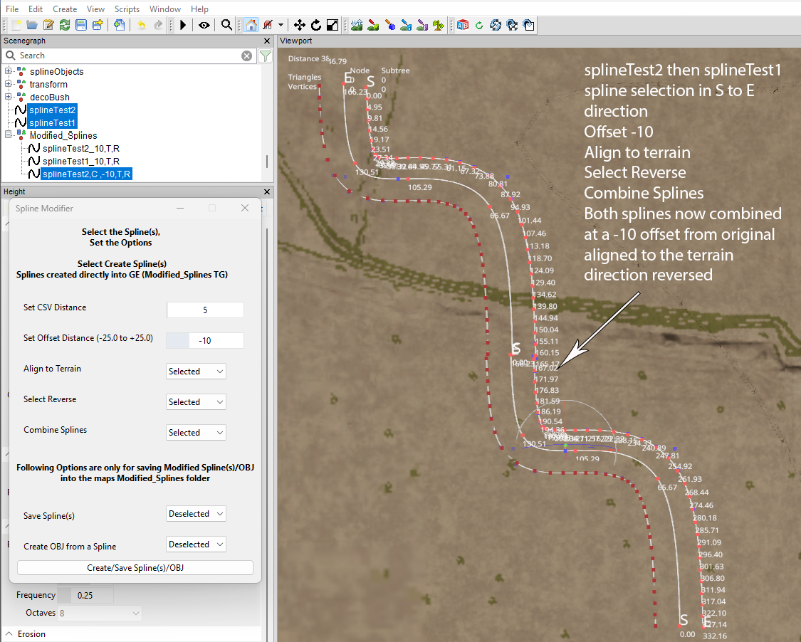
FS25 Spline Modifier Script (Updated)
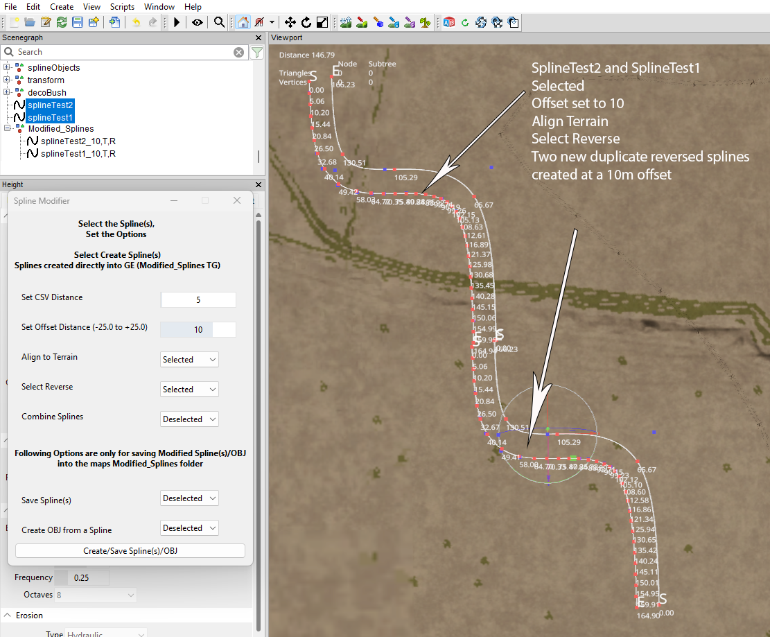
This script allows for the creation of several types of duplicate modified spline’s from a single or multiple splines
It will also reverse the direction of the duplicate spline(s) align them to the terrain and join several splines together to form one new spline depending on the option(s) selected.
Whilst individual splines can be selected and converted, if multiple splines are selected they must all be in the same direction starting from the first splines ‘S’ cv, this is also a prerequisite when joining splines using the Combine Splines option.
Installation
Unzip the FS25_splineModifier_Updated.zip (available at the end of this tutorial) and copy/paste the folder to the location of your GIANTS Editor 64bit 10.0.4/scripts folder in this case it is,
C:/Users/*****/AppData/Local/GIANTS Editor 64bit 10.0.4/scripts (replacing the *** with your computer name)
New Spline Modifier Panel
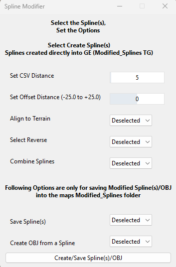
Overview
Set CSV Distance --- Allows for the distance between spline cv’s to be adjusted in the duplicate spline(s) (5m set as default)
Set Offset Distance --- This value is the distance a parallel spline will be placed away from the original, positive value (+) will place the
duplicate to the left of the spline when viewed from the ‘S’ cv negative value (-) to the right.
Value limited to -25m to +25 to minimise placement problems though some adjustment/deletion of
Spline cv’s may be necessary depending on the inner/outer curve radius of the original spline.
Note left/right (+/-) values are viewed from the 'S' cv so if a modified reversed spline is selected the left/right (+/-) position is also reversed.
Align to Terrain --- When selected will create a duplicate of the original spline(s) aligned to the terrain.
Select Reverse --- If selected will create a duplicate spline in the reverse direction of the selected spline cv’s
i.e S to E converted to E to S
Combine Splines --- This selection will combine multiple splines into one single spline.
NOTE: Splines must all be in the same direction (S to E) and selected in order i.e
Spline_1 S E, Spline_2 S E etc otherwise it will not work correctly.
Spline ends must be in reasonable proximity of each other but might require adjustment when splines
combined.
Combined spline name will be the first selected spline name.
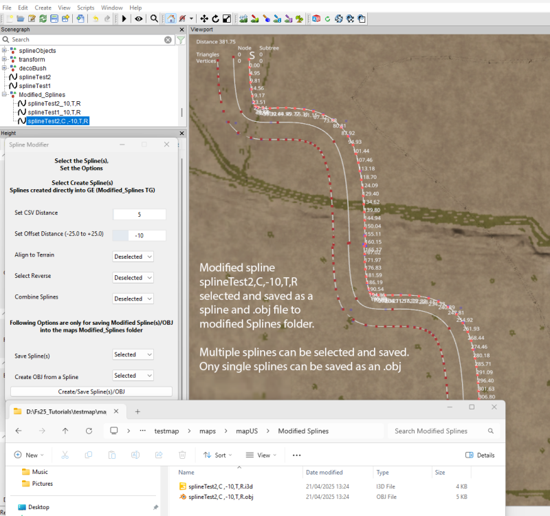
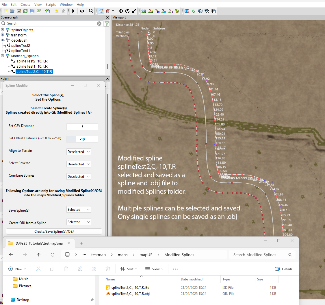
Separate section in the lower section of the panel enables saving of any selected spline(s) and conversion of any single spline to an .OBJ file both are saved in a new Modified Splines folder in the same location as the the map.i3d.
Save Splines -- Saves the selected spline(s) to the Modified Splines Folder.
Create OBJ --- Creates/Saves an .obj file of the selected (single) spline to the Modified Splines Folder.
Create?Save Spline(s)/OBJ --- Select this button to execute the script.
When first executed the script will create a new transform group in the Scenegraph called Modified_Splines, any splines created will be automatically loaded into the Scenegraph into this TG and a Modified Splines folder in the same folder as the map.i3d
When the duplicate splines are created they will have the following suffixes for reference depending on option selection
Suffix
'C' combined spline
'T' aligned to terrain
'R' Reversed
So spline with an offset of 8 aligned to the terrain and reversed will be
splineName _8,T,R
A combined spline with no offset aligned to the terrain will be
splineName,C_0,T.
If a modified spline is selected for further offset then the spline name will contain the first offset value followed by the second offset value
i.e splineName,C_-10,T_20,T would be a combined spline whose first offset is -10 from original spline and second offset 20 from the -10 offset.
Using the script
Create the spline(s)
Select the spline(s) – To select multiple splines, select the first spline and holding shift select the others in order
remembering to do it in the correct order if combining them
Select the relevant options
Select Create/Save Spline(s)/OBJ
Saving splines and converting to an .obj file –For splines -- Select the spline(s) (multiple splines may be saved) -- Select Create/Save Spline(s)/OBJ
For .obj file select a spline (only single splines can be converted at one time) -- Select Create/Save Spline(s)/OBJ
Both the splines and .obj will be saved to a Modified Splines folder located in the same folder as the maps.i3d.
Examples


FS25_splineModifier_Updated.zip
-
Added FS22 version
-
4x map Mask size ??
-
You are going to have to supply a bit more information like
Is it a mod you have created or something else regarding placeables ??
Also do your xml entries (nodes) agree with the i3d nodes
-
Here is a new way of creating roads in GE 10, still in pre release but worth keeping an eye on, in german but easily translatable.
https://www.youtube.com/watch?v=e2_4s4y_dGY
https://www.modding-welt.com/mods/file/3289-roadcreator-scriptpack-fs25-pre-release/I seem to remember something similiar before in FS15/17 but it was never released.
-
Quote
The mesh cooking warning appears anytime I apply a collision to an object regardless of what it is, but it never has any negative effects
By not having collisions assigned to objects vehicles/players will be able to drive/walk/fall through all other objects buildings/gates etc
The texture issue is caused by having the wrong texture/gdm/grle size for the map,
The following is a list of the grle/gdm sizes required for each map size, (dem sizes are the size after saving in map GE)
Normal 2k x2k map size
1. densityMap_fruits: 4096x4096
2. densityMap_ground: 4096x4096
3. densityMap_height: 4096x4096
4. densityMap_stones: 4096x4096
5. densityMap_weed: 4096x4096
6. infoLayer_farmland: 1024x1024
7. infoLayer_indoorMask: 4096x4096
8. infoLayer_navigationCollision: 2048x2048
9. infoLayer_placementCollisionGenerated: 1024x1024
10. infoLayer_tipCollision: 4096x4096
11. infoLayer_tipCollisionGenerated: 4096x4096
12. map_dem: 2049x20494kx4k map size
1. densityMap_fruits: 8192x8192
2. densityMap_ground: 8192x8192
3. densityMap_height: 8192x8192
4. densityMap_stones: 8192x8192
5. densityMap_weed: 8192x8192
6. infoLayer_farmland: 2048x2048
7. infoLayer_indoorMask: 8192x8192
8. infoLayer_navigationCollision: 4096x4096
9. infoLayer_placementCollisionGenerated: 2048x2048
10. infoLayer_tipCollision: 8192x8192
11. infoLayer_tipCollisionGenerated: 8192x8192
12. map_dem: 4097x4097 weight files 4096 x 4096
16kx16k map size
1. densityMap_fruits: 16384x16384
2. densityMap_ground: 16384x16384
3. densityMap_height: 16384x16384
4. densityMap_stones: 16384x16384
5. densityMap_weed: 16384x16384
6. infoLayer_farmland: 4096x4096
7. infoLayer_indoorMask: 16384x16384
8. infoLayer_navigationCollision: 8192x8192
9. infoLayer_placementCollisionGenerated: 4096x4096
10. infoLayer_tipCollision: 16384x16384
11. infoLayer_tipCollisionGenerated: 16384x16384
12. map_dem:8193x8193 weight files 8192x8192There is a lot of confusion over map sizes it all depends on how you refer to them if by the number of times anormal 2k x2k (4 square kilometers), 4kx4k (16 square kilometres)
Looking at a 16kx16k map then total area =256 sqK therefore the number of times a basic 2kx2k map will fit into that area is 64 times so in effect that is an 8kx8k map.
-
Two things spring to mind, first is the Error shown in your log (Warning i3d contains non indexed triangles, Warning Mesh Cooking BackRoad_Used_031 and possibly several others which cannot be seen on your image) that points to incorrectly created (I presume road) meshes, second is the use of One Drive its not recommended for either GE or for the Main Game as can lead to problems.
Another point as there is no shader details shown in the image what shader settings have you set.
QuoteA similar thing happens with the terrain deformation when driving around in game on this map.
I don't uderstand what you mean by the above statement, are you saying that you are having problems with deforming the terrain in GE ??
-
You could try this modified from this post
https://gdn.giants-software.com/thread.php?categoryId=4&threadId=15656
setAudioCullingWorldProperties(-8192, -100, -8192, 8192, 500, 8192, 16, 0, 0);
setLightCullingWorldProperties(-8192, -100, -8192, 8192, 500, 8192, 16, 0, 0);
setShapeCullingWorldProperties(-8192, -100, -8192, 8192, 500, 8192, 16, 0, 0);or
setAudioCullingWorldProperties(-8192, -100, -8192, 8192, 500, 8192, 16, 0, 9000)
setLightCullingWorldProperties(-8192, -100, -8192, 8192, 500, 8192, 16, 0, 9000)
setShapeCullingWorldProperties(-8192, -100, -8192, 8192, 500, 8192, 16, 0, 9000)from
https://gdn.giants-software.com/thread.php?categoryId=4&threadId=15658
or this one for 16x maps
-- Author:jcalv
-- name:JuotcaX16RandSolved
-- Namespace: local
-- Description:
-- Icon:
-- Hide: no
-- AlwaysLoaded: yes
setAudioCullingWorldProperties(-4096, -100, -4096, 4096, 500, 4096, 16, 200, 1000)
setLightCullingWorldProperties(-4096, -100, -4096, 4096, 500, 4096, 16, 200, 1000)
setShapeCullingWorldProperties(-4096, -100, -4096, 4096, 500, 4096, 64, 200, 1000)-
 1
1
-
-
As stated at the beginning of the tutorial Paint.net is not recommended as it only saves greyscale images as index color which cause GE to throw errors.
Gimp is highly suitable as it can save in all the necessary formats.
Regarding photoshop, there is no need to pay for the app, there is a free legacy version of Photoshop CS2 which does almost everything needed for Giants Editor/Farming Simulator creations with just a couple of free plugins (Nvidia dds plugin,Super PNG)
https://www.techspot.com/downloads/3689-adobe-photoshop-cs2.html
If you are creating a map for FS25 I suggest you have a look at the DEM Creation using QGIS Tutorial which describes how to align the overlay GE image directly onto and follow the the terrain contour so the sand and grass overlays only need to be created if you require them
-
I don't have that problem
You have of course updated the scripts,
Any new script update requires ALL the scripts to be downloaded again from the zip file at the bottom of the first post replacing any previous versions.
-
Updated Spline Paint Panel script -- 20/01/2025 Random value problem fixed and UI Changes
-
1
-
-
Don't think so (then again FS25 is a strange bird) main criteria is to double the size of all the files in the map data folder (grlr/gdm/info/weight).
There are several premade Blank 4x maps available on line which would save you time
-
There are many reasons why this happens,
1. the textures are not solid but are partial (alpha layer controlled) and it depends on what position the editor places the texture (in your cas you are using a single texture not a combined one)
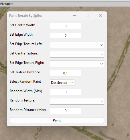
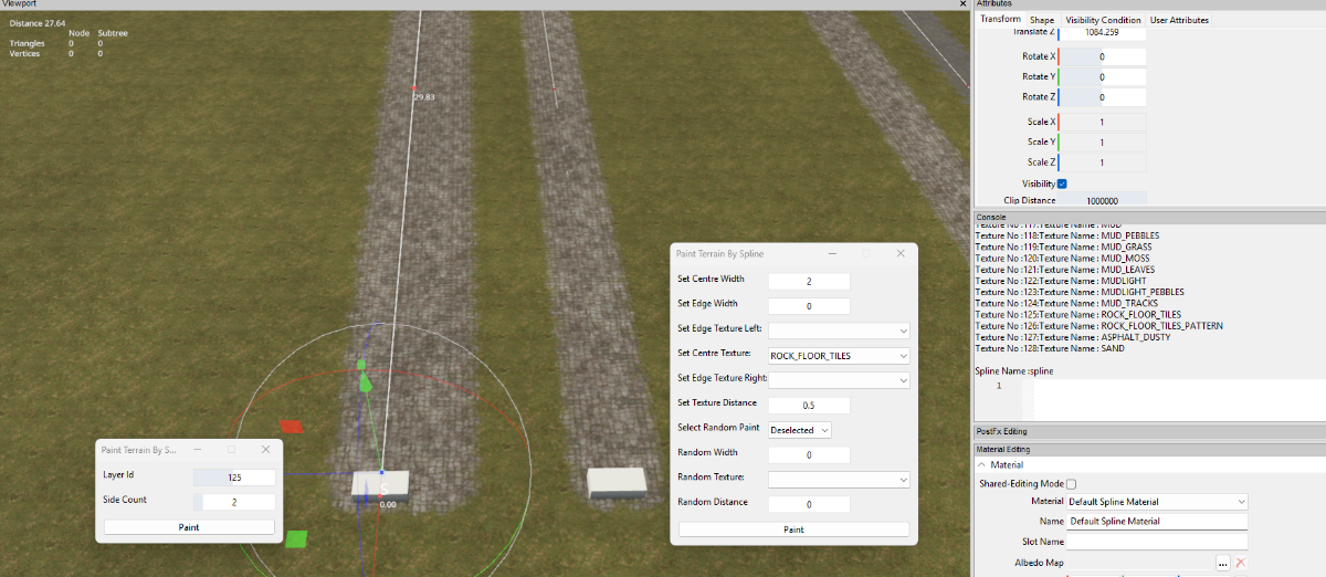
2. When painting the terrain using a spline it depends on where the spline is placed relative to the terrain mesh as painting is only done on a full terrain mesh section.
The following image shows two identical splines painting identical textures and widths the two cubes are 2m wide to give a width reference
Left hand spline is using the editors inbuilt Paint Terrain by Spline script
Right hand is using the FS25 version

You will also notice that when painting the terrain either by script or brush you will never get a straight edge this is due restrictions detailed above.
If you wish to have a path with straight edges then you have to create a mesh in a 3d modelling programme (Blender )texture and texture and import it as an i3d then after positioning select the terrain decal option in the Shapes tab.
There are many prebuilt roads/path kits available on line with straights and curves.
-
-
Just found this little video from StrauntMaunt that may help you, he shows how to create fields in less than a minute,
https://www.youtube.com/watch?v=pzRxjy2K_To
-
Have you tried using the Giants Studio/Debugger to check your script, a video on how to use it is available here
-
Have you checked the Vehicle maintenance mods already on modHub for reference,
-
The spikes could be caused by enlargement of the dem in QGIS caused by the point cloud data.
There is a problem in the gdal translation between different data types and CRS's so it might have been bettwer to source something other that Point Cloud data.
As I mentioned in the tutorial I had the same sort of 'terracing' when changeing CRS.
-
Not to sure what you mean by discharges, unless you are refering to creating the fields parallelogram in which case there may be (as they are both painted into an infolayer or mask).
-
Try updating to the latest FS25 scripts 08/01/2025
-
Yes, its worth a try as it makes a lot of things simpler and is being updated all the time with new stuff
-
Scrits update 07/01/2025
Various changes to UI's
fencePower Placement script Stay Upright option deleted - causing intermittent rotation placement problems
FS25 Spline Modifier Script (Updated)
in Mapping
Posted
You will note that the scripts that are specifically for FS25 in your image are already annotated with FS25 or 25 so I don't see a problem.
The other scripts mentioned ( three of which were definitely not created by me) may work with other versions