


WrinkleysRule
-
Posts
419 -
Joined
-
Last visited
-
Days Won
94
Content Type
Profiles
Gallery
Downloads
Events
Forums
Articles
Posts posted by WrinkleysRule
-
-
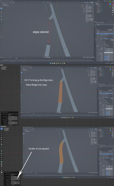
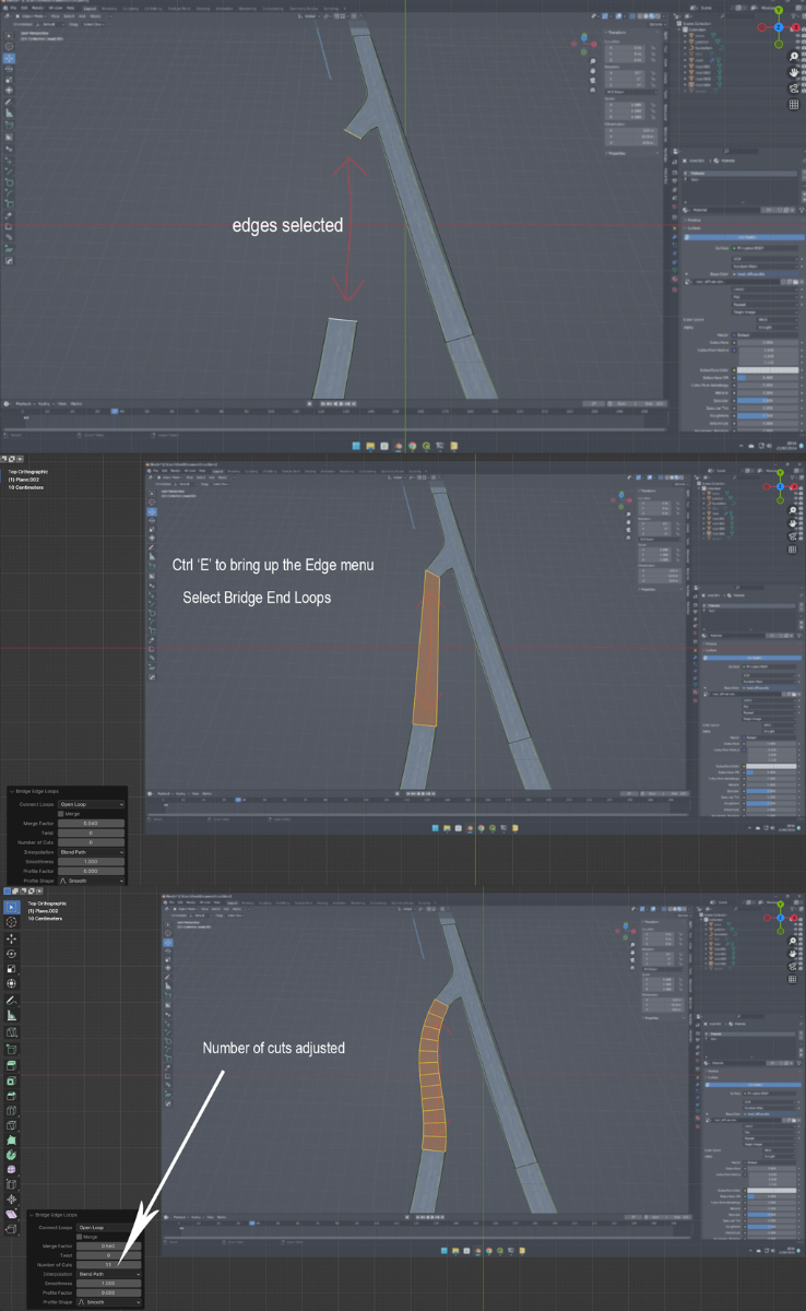
Even quicker method,
Using your original image as a background
Two Edges selected
Ctrl 'E' to bring up the Edge Menu
Select - 'Bridge Edge Loops'
Adjust Number Of Cuts to suit -in this case 11
Example in image below
-
Another method which may seem long winded at first is to select the tjunction edge and the incomeing road edge in edit mode 'edge select' subdivide once.
Change to vertex select select the two new vertices and press 'F' on the keyboard, this will create a edge between thew two points.
select this edge and subdivide three or four times.
'Following excert from the Export a Spline from Giants Editor into Blender to Create Roads/Railways (Updated)'Change to Object Mode, with the edge selected –Select , Object—Convert—Curve , this converts the mesh to a curve ready for use with the Curve Tools.
Select the Curve Icon in the Scene panel (green semi circle) to open the Curve Tools Panel
With the curve still selected change to Edit Mode
The new curve first needs to be aligned along the correct axis for the road, to do this you can either select
Control Points—Tilt and type 90 or simply (Ctrl ) -- T -- 90
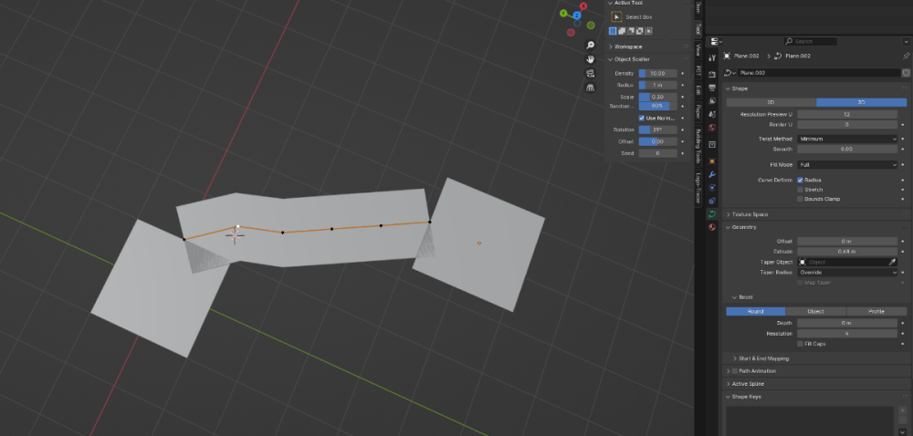
In the Shape panel of the Curve Tools, select 3D, Fill Mode 'Half', Curve Deform 'Radius Selected', all other settings can be left as is.
Open the Geometry and Bevel Tabs
Geometry Tab
Extrude ‘ 3 ‘ ---this equates to a road bed width of 6 metres , half the desired width or your roadbed width
Offset ‘ 0 ‘ ---value can be left at 0 as this just raises or lowers the mesh by +-1m
Bevel Tab
Select -- Profile
Depth ‘ 2 ’ -- this figure is the width of the road edges in metres, in this case 2 for 2m
Resoloution – ‘ 0 ’ --This figure sets the number of subdivisions in the edge mesh should you wish to create
your own custom or preset profile.
You should now have a road mesh between the tJUnction and the incoming road that can be adjusted to suit your needs obviously further subdivision of sections of the roadbed may have to be done to create smoother curves.
example in image.
-
Would help if the junction was the same size as the road but I would change the angle slightlyof the junction and just join the roads with another mesh
-
Check the zip folder as you may have an extra folder, also you do not need to zip a file/mod unless you are going to use it in multiplayer so a quick test to see if your problem is the zip or the edited map folder would be to place the edited folder directly into the mods folder and see if the map appears in the map options.
-
The log file you sent me shows a problem with the Sterneldioten i3d exporter you are using.
I have sent you a pm with a way of setting up the exporter to work correctly and also a link for you to update the version (i3dio.exporter:export_blend_to_i3d:INFO: I3D Exporter version is: 0.0.0) you are currently trying to use.
Link added in case others need to update their versions.
https://github.com/StjerneIdioten/I3D-Blender-Addon/releases
-
Did you make sure Border_1 selected and in Object mode export it.
-
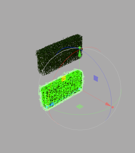
Normally happens if the items transform point is in the middle and not at the beginning but can also occur if spline transform is not zero on rotation which could be the case as the hedge appears to be following the splines rotation
-
Short answer is no, the CSV script basically allows the user to create a 2d spline (using INSERT and CRTL B foe example following a road layout on a GE png overlay) it then samples the terrain height at a user set distance along the 2d spline and creates a 3d spline for use with the terrain height scripts.
So the method you are using would still have to be done to create the spline with increased number of spline nodes on the curves to get a smoother terrain once the terrain height script has been used.
A script could be created that uses the road section transform group (i.e A_Road_50m) as a csv point but the problem would arise when a curve is encountered as the there is only one point (TG) which would when the terrain script is activated produce a straight line.
Personally I prefer to use the Blender method ( see the Export a Spline from Giants Editor into Blender to Create Roads/Railways (updated) tutorial ) for creating roads as it is far more flexible, you can of course still use the prefab textures for the road or create your own.
-
This is sometimes caused by GE not recognising the attributes set by the script
In GE select the fields TG and in the User attributes delete and then re enter the FieldUtil.onCreate entry.
This problem has been addressed in the tutorial
fieldsNew -- containing a fields transform although this will have the FieldUtil.onCreate attribute set by the script I suggest deleting the attributes
and reassigning them by Add New Attribute --Type --scriptcallback -- onCreate -- Add and in the new onCreate box enter FieldUtil.onCreate
as sometimes GE doesn't recognise some script set User Attributes.Also make sure that there is only one Field.Utils.onCreate in the map that you are using in gameI have now updated the tutorial to make this a bit clearerfieldsNew -- containing a fields transform although this will have the FieldUtil.onCreate attribute set by the script
I suggest if copy/pasting the fields TG from the fieldsNew TG to the gameplay folder, delete the attributes and reassign them
by Add New Attribute --Type --scriptcallback -- onCreate -- Add and in the new onCreate box enter FieldUtil.onCreate
as some times GE doesn't recognise some script set User Attributes consequently field no's may not appear in game. -
Another soloution could be to open the gameSettings.xml (\My Games\FarmingSimulator2022) and look for <ingameMapFilters>0</ingameMapFilters> and set the number back to 0.
This problem was caused by a version of Courseplay so maybe your base map has a corrupt gameSettings.xml
-
Field numbers are taken from the i3d and positions are taken from the fieldMapIndicator so make sure your fields transform group is correct and the nameIndicatorIndex is set to 1
Hierarchy:-
fields
|
field01,
|
fieldDimension (index0),
|
fieldMapIndicator (nameIndicatorIndex(1),
Farmlands however are taken from the farmland(s).xml and show up in the map overlay when you select the farmland box at the bottom
The numbers may not match depending on farmland size/position
-
The base game Alpine shows 'farmlands' mapUS, mapFR both have 'farmland' so to avoid this you can add "farmland.xml" to the local farmLPath array.
Though it does say in the instructions at the top of the script :-
"if the farmlands.xml is in a different final path or is a different name to the ones in farmLpath then ---
---- just add the new path/name to the 'farmLpath' array."Edit:- Field Dimensions and Farmlands.zip upadate to include "farmland.xml" to farmLPath array.
-
I will have a play around and see if I can replicate this problem.
-
 1
1
-
-
You did start off with a blank info layer as that can sometimes affect the result.
-
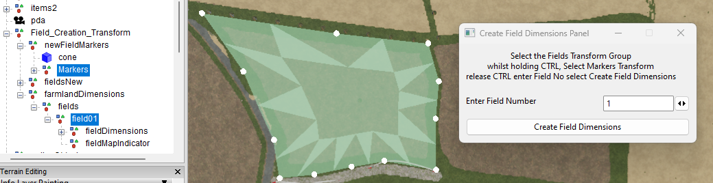
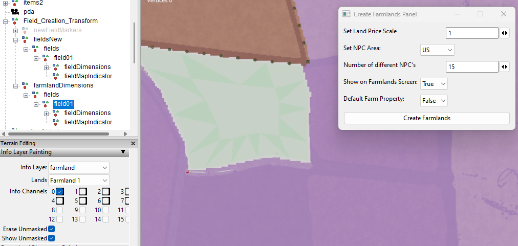
Below are two images which show how I create the farmlands.
The first shows the new field dimensions for the farmland area. Note : the farmaland area includes the field boundary as well otherwise you will have to buy a seperate parcel of land as well as the field.
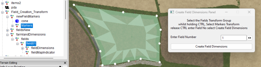
The second screenshot shows the farmlands area painted and selected in GE in the Info Layer Painting

-
I have just downloaded and tried the script several times and I am getting no errors in execution.
The error points to a problem in the field dimension creation so I suggest you check/redo the Create Field Dimensions script and see if that helps.
For the farmland paint to show up in GE the Terrain Info Layer Paint Mode must be selected and the relevant Info Layer 'farmland' and Lands (field no) must be selected.
Nothing to do with the error but bit curious about this double folder entry
C:/Users/Brummie Farmer/AppData/Local/GIANTS Editor 64bit 9.0.6/scripts/Field Dimensions and Farmlands/Field Dimensions and Farmlands/Create Farmlands Panel
-
Open windows explorer select the the three dots at the top
In the dropdown select options
In the folder options pop up select view
Under Hidden files and folders
select Show Hidden files,folders and drives
Select apply
app data folder should now be visible in C:/Users/******-
 1
1
-
-
I am a bit confused as to what you are trying to achieve, if you want a 'farm' area of 12k x 12k then simply create a 16k x 16k map and only use the 12k x 12k section leaving the 4k surplus as a border area then if rquired add a further border mesh to get the overall 20k x 20k area you seem to want (judging by your KMZ files).
-
To get a proper dem you will need to combine all the 26 tiifs into one single tiff using a programm such as QGIS this will then even out the different shadings and gaps usually found when importing UK lidar directly into Google Earth.
The following is one combining method using QGIS
QGIS
download from here
https://qgis.org/en/site/ --approx 1.2gbOnce downloaded/installed in the folder QGIS 3.36.0 select QGIS Desktop 3.36.0
select Plugins
You now require the following plugins
Virtual Raster Builder -- may need to be reinstalled (without uninstalling) to remove error message
go2streetview
Google Earth Engine
Grass GIS provider
KML Tools
LAStools
Raster Cutter
Once you have the plugins installed Select Project -- Properties - CRS and ensure the EPSG:27700 - OSGB36/ British National Grid
is selected (tip in filter type 27700 to bring up the correct entry to select) this setting is important for alignment between the different CRS of Google and OSGB which causes the splits between rasters when imported directly into Google Earth.
Next Settings -- Rendering -- Raster -- Contrast Enhancement -- Single Band Grey --Stretch to min/Max --selected in dropdown
Drag and drop all the Defra tif images into the the main screen they will open in seperate Layers
Now select Raster -- Miscellaneous --Build Virtual Raster
At the end of the Input Layers box select the 3 dots this will bring up another pop up with a list of all the layers in your Layers panel
Select All then Run
A new Layer will appear named Virtual with all the selected Layers merged into one image with the correct brightness/contrast
To save this virtual file as a tif right click on it Export -- Save As
in the 'Save Raster Layer as' pop up
Select Rendered Image
Select the three dots at the end of the filename box to open a file browser add file name Save
and in Save Raster layer pop up select OK
Open Google Earth and drag drop new file into itNOTE: The CRS EPSG:27700 - OSGB36/British National Grid setting only applies to UK Lidar for any other SRTM Tiff the setting has to be changed to match that tiffs CRS.
-
@c.christensen98
Pm me the coordinates of your Geo. tiff (ie. n51_w003_1arc) and the site you downloaded it from and I will see what is going on with this continuing 'whiteout'.
-
@deboy130
As far as I'm aware you cannot create a 45x map all maps have to be to ^2 i.e 2,4,8,16,32 64 etc
see this list of map dem/gdm/grle sizes required for the various size maps (courtesy of Bonger76)
Normal map size
1. densityMap_fruits: 4096x4096
2. densityMap_ground: 4096x4096
3. densityMap_height: 4096x4096
4. densityMap_stones: 4096x4096
5. densityMap_weed: 4096x4096
6. infoLayer_farmland: 1024x1024
7. infoLayer_indoorMask: 4096x4096
8. infoLayer_navigationCollision: 2048x2048
9. infoLayer_placementCollisionGenerated: 1024x1024
10. infoLayer_tipCollision: 4096x4096
11. infoLayer_tipCollisionGenerated: 4096x4096
12. map_dem: 1025x1025
4x map size
1. densityMap_fruits: 8192x8192
2. densityMap_ground: 8192x8192
3. densityMap_height: 8192x8192
4. densityMap_stones: 8192x8192
5. densityMap_weed: 8192x8192
6. infoLayer_farmland: 2048x2048
7. infoLayer_indoorMask: 8192x8192
8. infoLayer_navigationCollision: 4096x4096
9. infoLayer_placementCollisionGenerated: 2048x2048
10. infoLayer_tipCollision: 8192x8192
11. infoLayer_tipCollisionGenerated: 8192x8192
12. map_dem: 2049x2049
16x map size
1. densityMap_fruits: 16384x16384
2. densityMap_ground: 16384x16384
3. densityMap_height: 16384x16384
4. densityMap_stones: 16384x16384
5. densityMap_weed: 16384x16384
6. infoLayer_farmland: 4096x4096
7. infoLayer_indoorMask: 16384x16384
8. infoLayer_navigationCollision: 8192x8192
9. infoLayer_placementCollisionGenerated: 4096x4096
10. infoLayer_tipCollision: 16384x16384
11. infoLayer_tipCollisionGenerated: 16384x16384
12. map_dem: 4097x4097-
1
-
-
@c.christensen98, see the note in the Microdem section of the tutorial
Note:
Some SRTM’a display a completely white images in Google Earth, if this happens open the SRTM in Microdem and follow the above steps to modify the Display Parameters. -
-
The CSV script is primarily for use where the spline is created away from the terrain for example tracing the road layout along the Google Earth Layout image then executing the script so that the new spline follows the terrain contours and road shape.
It can also be used to crete a rough spline path with minimal CV's and then create a new spline with a chosen number of CV's for greter accuracy when setting terrain height and road layout.

Create Field Dimensions and Farmland Tutorial
in Mapping
Posted
The scripts only set up the field/farmland areas and have nothing to do with the actual crop planting/harvesting and as everything works when harvesting and getting chopped straw out the rear of the combine the problem with switching to swathe is more likely to be with the combine.
Without knowing which combine you are using its difficult to pinpoint any problems.