


WrinkleysRule
-
Posts
419 -
Joined
-
Last visited
-
Days Won
94
Content Type
Profiles
Gallery
Downloads
Events
Forums
Articles
Posts posted by WrinkleysRule
-
-
Are you using the latest scripts for FS25 ???
-
The power poles I used are from the FS22_PowerTelegraphPackBB_prefab https://www.farming-simulator.com/mod.php?mod_id=248932&title=fs2022
It will work sometimes with a extra transforms in the wire mesh but there are times when the wire with the extra tg child will appear in the wrong place.
I have tried placing a bird(s) along the wire by just adding them to the wire_FenceNode but that had the same problem sometimes with them upside down.
If you use a blank transform seperately in the wire_fenceNode it will simulate a missing wire.
As to the problems with your map you could first try deleting the shader cache in the C:\User\Your Computer Name\AppData\Local\GIANTS Editor 64bit 10.0.3 folder and re opening the map in GE.
Make sure you have any scripts in the C:\Users\Your Computer Name\AppData\Local\GIANTS Editor 64bit 10.0.3\scripts folder not in any of the C:/ Program File folders
Failing that if you create/Use a new map you can copy/import most of the stuff from one map to another including data files such as dem and weight files grle/gdms etc providing you use the same base map of course (Alp/FR/US)
Finally if you have access to Google drive etc upload the map to that and send me the link via Personal Message and I will take a look at it to see what is going on.
-
Quote
I have done is place the 70m cable into "wire_fencenode" and the pole object into "postObject"
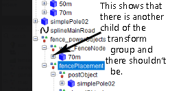
The 70 m cable transform group shows that there is another child( chidren of the mesh) check my wire_fence nodes for correct mesh
Please post a picture of the fencePowerObjects transform showing all the children of all the transform groups especially the 70m and simplePole02 meshes.
Regarding tutorials I suggest you follow the one on this site as I don't recomend using third party tutorials as they sometimes miss points or add points that are wrong in the case of the tutorial mentioned he adds a transform group to the wire which is wrong.
GE is the only software that can directly be used to create maps there are others but in the end they all have to have their work/creation inputted into GE.
As you can see I have no problems in using either of the scripts so the problem appears to be at your end one other thing to try is to close GE and re-open as I have noticed with this version scripts tend to hang after a while and the Re-int Script Enviroment icon doesn't seem to do anything.
As I suggest in all the tutorials, try and test/experiment with the scripts on a blank map before using on a map that is being created to get used to them and see what can/cannot be done.
Given that you have had scaling problems with splines before double check that any splines you have created DO NOT have any Rotation/Scale if they do then Freeze Transform Rotation and Scale (NOT Translate)
-
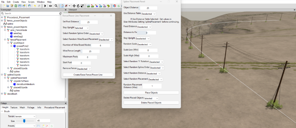
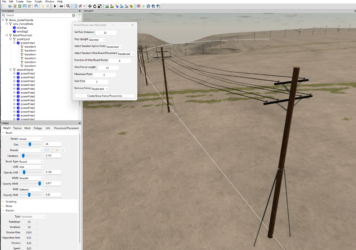
No problems with the FencePower placement script my end however I have noticed that you haven't set up your wire_FenceNode correctly the node/mesh should only be one mesh and not be part of any other Transform Group
Also it is worth noting that once the script is executed and the TG's are created if the script is closed and then re executed another set of TG's will be created these MUST be used otherwise the script will not work.
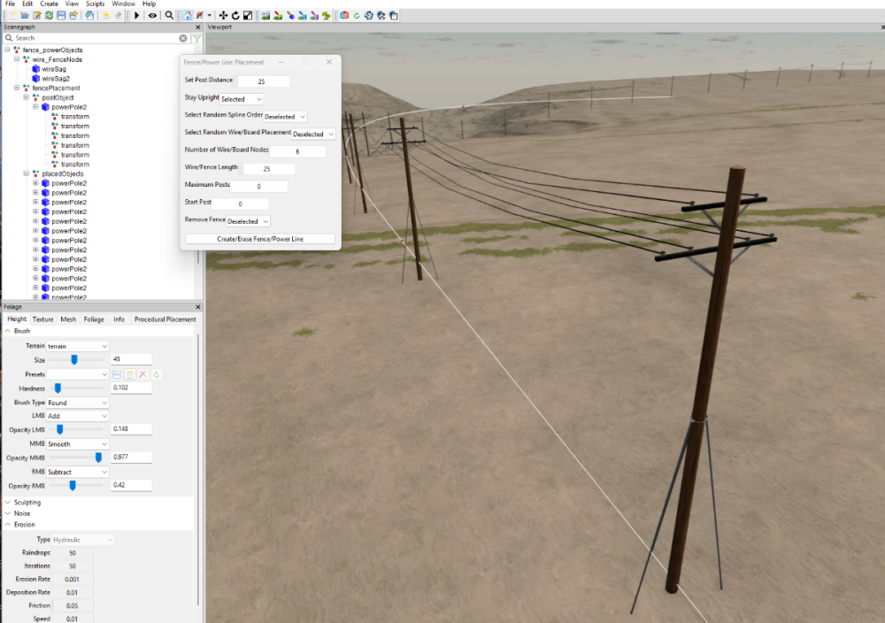
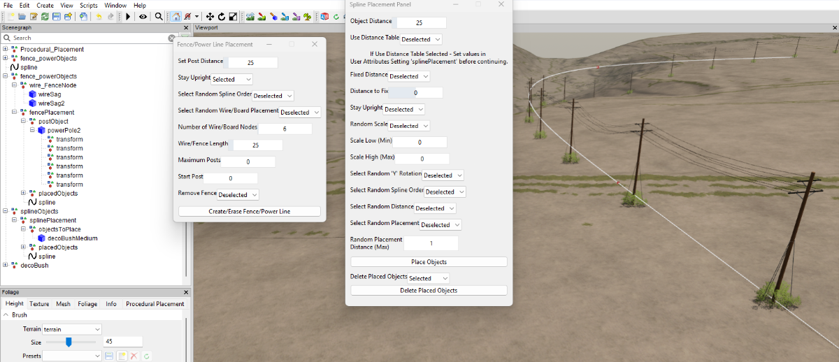
As to the spline placement problem it appears from the Number of Objects Placed value that it seems tobenot recognising the spline and placing is -1 I suggest you close the script and re execute it and try again, the Place Objects button should only have a blue colour when the script is running.
Another point why do you keep saving the map ???, you have several onSave messages in the console there is no need to keep saving the map everytime you do something unless you have poor computer specifications.
Scroll the consol list to check for error messages, if in doubt check the editor log in C:\Your Computer name\ccrjs\AppData\Local\GIANTS Editor 64bit 10.0.3 folder.
Further check using the spline placement to place a bush at the base of the poles.
-
The purple layer problem has been mentioned and reported several times on the main forum.giants-software.comYou could try and adjust the Profile settings in GE -View - Profile, I have found by switching Settings can sometimes remove it temporarily but it will come back the next time you open GE.
Regarding the Fence Placement script this has nothing to do with the purple layer.
You appear to be using the script incorrectly, the fencePLacement transform must be selected when running the script otherwise it will not work, also when you first execute the script a set of transform groups are created these must be used, if however you close the script and execute it again you MUST use the new transform Groups that are generated if you try to use the first set created the script will not work.
-
You can have whatever shape spline you want, its entirely up to you how the railway looks.
You can loop the spline underneath the map and bring it back to the start and join the spline ('O' toggles the function on/off) which will give the effect you mention
-
I don't know about steam but as far as I'm aware the game in multiplayer only checks to see if each player has the required mods.
There are some problems with multiplayer and certain effects i.e. any terrain deformation done on one map does not show an another players map same with tyre tracks and a few other things.
The main giants software forum has several posts on multiplayer problems here is just one
https://forum.giants-software.com/viewtopic.php?t=211504
Could any problems be linked to the .I64 files in the map folder ???
-
You can place items along a spline at set distances either by Using the Set Object Distance value or by the Use Distance Table see the relevant tutorial for their use,
Regarding railways and roads you will only be able to place stright sections as the spline will not automatically 'bend' rail or road meshes.
For custom rail/road meshes It is best to create them in Blender using the spline as a reference then export (as i3d) the finished mesh into GE as an i3d described in the following tutorial
-
Possibly a spammmer but, if you had bothered to check the topics you would have seen that the script has already been updated on th 2/12/2024
-
For those having problems creating new procedural scripts it may be necessary to start Giants Editor in Adminstrator mod ( Run as adminstrator) to allow the scripts to be created in the base game files.
There doesn't seem to be a way of specifying a different directory for the custom scripts to avoid any accidental complications when changing base game files.
-
I see, thats interesting and is going to cause a few problems if not addressed by Freeze Transformating before using any scripts, in Giants Editor 9.0.6 you could only move the spline .
This probably a result of the scaling being allowed on the SpineSurface mesh and Giants not restricting it when using a normal spline.
-
How did you manage to scale the spline as it cannot be done in directly Giants Editor??
-
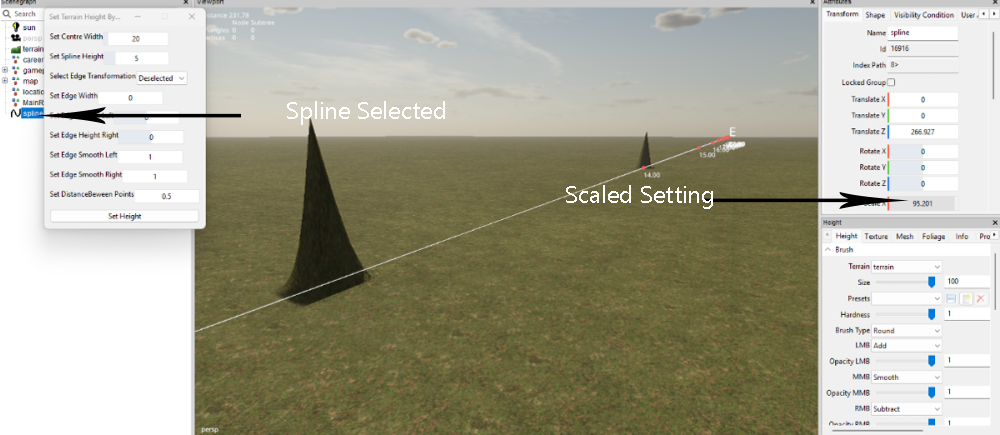
No problem in setting the height using that script,
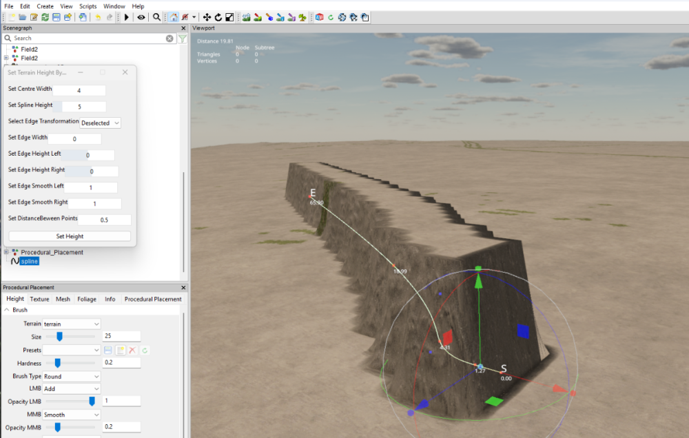
But I have just noticed you have somehow managed to Scale the spline (This section is normally greyed out so adjustment cannot be made) , a spline should not have any Rotation or Scale if any is set then you must Freeze Transform both Rotation and Scale
Edit - Freeze Tansformations -- and select Rotation and Scale (NOT translate)
-
You haven't specified any Centre Width, as you are new I suggest you have a look at the tutorials for these scripts which explain how to use them
-
Thank you very, very much for your time and effort, its just what we were looking for, it is brilliant now we have a great grounding in Procedural Placement to work from using this example.
I will now spend a couple of hours watching your full tutorial on youtube and look forward to any more FS25 tutorials you may have in the pipeline.
-
 1
1
-
-
Some further information on this method would be appreciated as information on the Procedural Placement Tools is severely lacking. (as is most of the info regarding Giants Editor)
-
I have updated the Spline Placement Panel Combined script anp laced it in the zip folser on page one of this topic.
The update is just an interim fix that removes the first item placed from the start of the spline which alleviates the first object placement problems, however I will continue to investigate why this is happening.
-
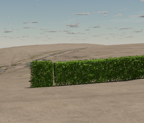
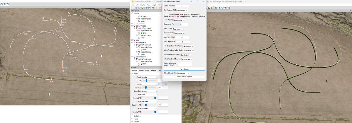
Thats good to know, the first post problem may be due to the problem I noticed in the earlier post, this first hedge problem (shown in the previous post) is caused by the point of origin being in the centre of the object and the script not allowing for this extra length.
I have an update nearly ready which should solve this problem just need to do some further tests to make sure it works as intended.
-
The terrain height script is the only one that will 'smooth' the terrain but if you mean a script which will just smooth the terrain in a wide area along a spline and keep a varying terrain height then no I don't think I have seen one that can do that.
-
I don't seem to be having that problem using 4splines from different directions I get this.

I do however have a problem with the first hedge being placed in an upright position which is a throwback to an old setting of placing at the start that I have just noticed
which I shall now take a look at.
-
DEM Creation using QGIS Tutorial
For this tutorial you will need the following programmes and items
Google Earth Pro --- https://www.google.com/earth/about/versions/#earth-pro
QGIS --- https://qgis.org/download/
Overlay.zip --- Attached at the end of this tutorial
Download Google Earth Pro and QGIS (may take a while as QGIS is approx 1.2Gb)
Unzip the Overlay.zip and place the Overlay folder into you map root folder
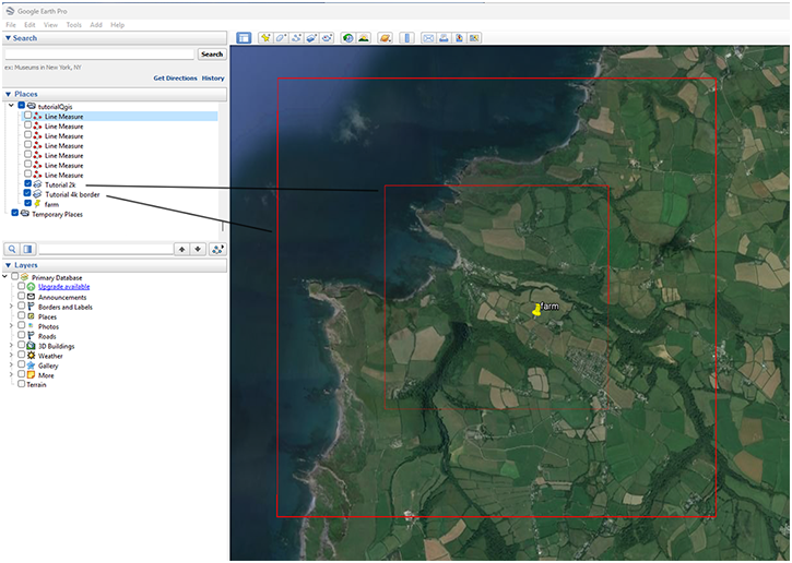
Create Farm Marker
This section details how to create a marker that outlines your proposed farm area for use in QGIS and is basically the same as first part of the previous tutorial, DEMs and Borders the Easy Way.
Once both programmes are installed open Google Earth Pro –
Select the Temporary Places icon and right click any where in the Places panel,
Select- Add –Folder name this folder with your map name (this is to keep all your files in one folder).
You may need to drag drop any newly created files into this folder.
Ensure the Terrain Icon in the Layers panel is deselected
Navigate to your proposed farm location
Create a vertical and horizontal 2.1km line using the ruler tool centred roughly at the middle of your proposed area
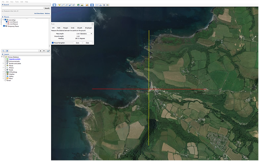
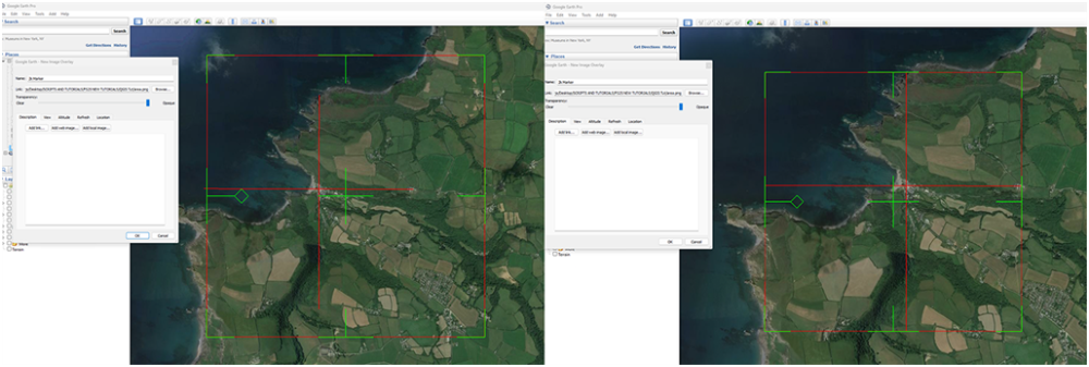
Select the Add image Overlay icon in the Toolbar (green markers will appear) and browse to the Overlay folder location and Select Area.png, rename to 2k Area don’t close the Image Overlay pop up at this time.
You will see a red square with green markers, adjust the edge markers (T shape) to fit the horizontal and vertical lines previously made this will give you a 2.1k square which you can move over the location to finalise the area by means of the centre cross or rotate using the diamond (if you move any of the corner markers you will distort the square and have to reset the edges). Once you are happy with the position click OK.
If you wish to move it again right click on the 2k Marker in the Places panel and select Properties this will bring the adjustment markers back.
At this point mark and name the area using the Add Placement tool as when adding the Lidar Data/SRTM Google Earth zooms right out so the Markers may not be visible for you to centre the cursor on to scale the relevant Geo.tif
Should you wish to create a border around your 2k area then, using the ruler tool create 1k lines away from the edge of the 2k area. 1k chosen for performance reasons but if you want a bigger border just increase the distance.
Select the Add image Overlay icon in the Toolbar and browse to the Area.png location and select it, rename to 4k Border and repeat the alignment detailed above.
In the Places Panel right click the 2k Area icon and Save Place As .kml (in a suitably named folder) do the same for the 4k Border Area if needed.
Obviously if creating a larger map change the markers to an appropriate value.
The Line Measures can now be deselected leaving just the two markers
Finally save the My Places -- File – Save – Save My Places
Creating the DEM
Different Countries will have different methods of downloading data so check the relevant Sites methods.
For this tutorial I will be using UK Lidar Data available from -https://environment.data.gov.uk/survey
Open in browser zoom in to your location Select Draw polygon, Draw polygon round the farm area (right click move to next point until your shape is complete double click to finish)
Select - Get Available Tiles
Select Product --LIDAR Composite DTM --- This produces a ‘terrain only image’, DSM will produce all buildings trees etc image.
Select Year -- Latest year currently 2022
Select Resolution – 1m - higher 2m resolution will have smaller file size
1m resolution files will have a file size of approx 80kb per tile.
Select - Download All and save to a suitable folder (the one you saved the 2k/4k Area .kml’s)
Create another folder in that folder and name it Your Farm Name Tifs
Unzip the downloaded files and copy paste the DTM_1m.tif images into this folder.
QGIS
I will be using QGIS 3.40.0 throughout this section later versions may become available so version numbers may change.
All the programmes required for QGIS should in a folder on your desktop after installing QGIS 3.40.0
In the folder QGIS 3.40.0 select QGIS Desktop 3.40.0
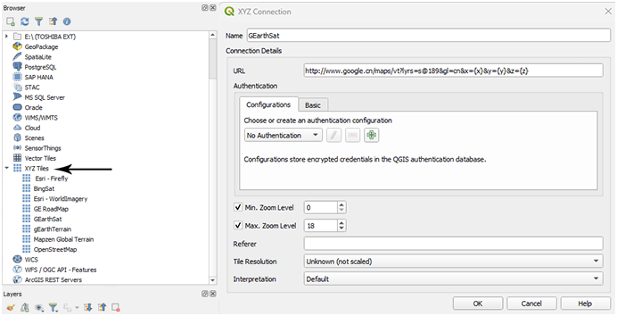
In the Browser panel check to see if you have a Google Earth overlay in the XYZ Tiles icon ( this overlay will only be used as a reference).
If you do not have the Google Earth Satellite overlay then right click the XYZ Tiles icon and select
In the Pop up panel enter a suitable name (eg Google Satellite) and in the URL panel copy paste the following
http://www.google.cn/maps/vt?lyrs=s@189&gl=cn&x={x}&y={y}&z={z}
the rest of the settings can be left as is and click OK.
Should you prefer or want to add others then do the same as above here are some
Open Street Map
https://tile.openstreetmap.org/{z}/{x}/{y}
Bing Maps
http://ecn.t3.tiles.virtualearth.net/tiles/a{q}.jpeg?g=1
Google Satellite Hybrid
https://mt1.google.com/vt/lyrs=y&x={x}&y={y}&z={z}
Other map tiles can be found here, bear in mind some may require an API key.
https://www.geohowtos.com/howtos/xyz-tiles/xyz-tiles-qgis
In QGIS double click on the Map Tile you want to use, it will open with a complete map of the world, don’t bother zooming in yet.
Input Lidar/SRTM Data
The following method is the same for both Lidar and SRTM data in this instance I am using Lidar data
Drag and drop the Lidar tif image(s) (if more than one select all) into the QGIS main screen they/it will open in the Layers Panel, if more than one then they will be listed separately in the Layers Panel.
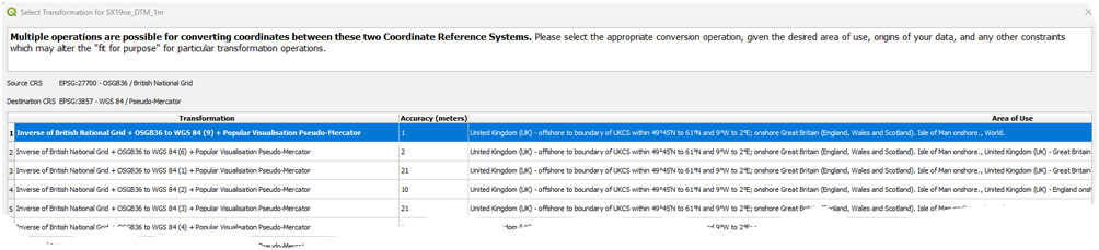
If you get a Select Transformation pop up as shown below

when adding data Select -- Cancel this will keep the original CRS of the data otherwise distortion of the data will occur.
Right click on any of the layers and Select- Zoom to Layer, this will zoom to the layer image with the Map Tile reference layer underneath.
If only one Layer (Lidar tif image) skip the next section
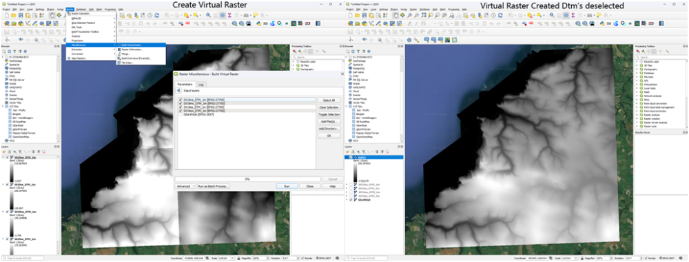
Multiple Layers
If more than one layer Select --Raster -- Miscellaneous --Build Virtual Raster
At the end of the Input Layers box select the 3 dots icon this will bring up another pop up with a list of all the layers in your Layers panel
Select the Lidar tif image(s) then Run
A new Layer will appear named Virtual with all the selected Layers merged into one image with the correct brightness/contrast
If you want to save this Virtual file for future reference, in the Layers Panel right click on the Virtual entry and Select - Export -- Save As
In the 'Save Raster Layer as' pop up
Select –Output Mode -RawData
Select the three dots at the end of the filename box to open a file browser navigate to where you want to save the file add file name then Select Save and in the Save Raster Layer pop up select OK.
Clip the image tif to the 2k (4k) size
If necessary right click the new Virtual (or Single) Layer and select Move to Top this will place the image above the Map Tile layer
Or middle mouse button select and drag to the top of the Layers panel.
Drag the 2k Area.kml saved earlier into QGIS and in the pop up Select Add Layers depending on the .kml/kmz used there may be two Layers one will have the marker colour the other will be the marker shape file it is the shape file that is required for the next step, if both shown in the Layers Panel deselect the one with the three colour bands.
Select – Raster – Extraction –Clip Raster by Extent
In the pop up panel
Input Layer - in the drop down Select the Virtual (single) Layer
Clipping Extent --- Select the arrow on the far right, in the dropdown –Calculate from Layer and select the 2K Area shape file
Clipped Extent--- Select the Arrow far right and Save to File, browse to where you want to save this file, name the file and Save as Type *.tif
All other settings can be left as is
Select-- Run
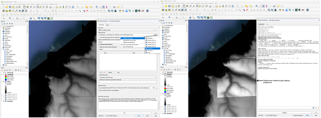
The clipped image will not be aligned to your marker but be slightly rotated this is because the marker has a different CRS to the Virtual Layer.
This seems to only affect data in the EPSG:27700 - OSGB36/ British National Grid format.
If someone a bit more QGIS savy can show how to correct this I would appreciate it. I have tried re-projecting all Layers to both the British National grid
and the default Google earth EPSG:3857 but without success and as stated previously converting from EPSG:2700 to EPSG:3857 creates artefacts in the image.
Right click the new 2k clipped layer and Select – Export – Save As --in the Save Raster Layer as.. popup
Select Output mode – Raw Data
File Name – Select three dots icon and navigate to where you want to save the file – name and save
Extent(Current:Layer) –Calculate from – in the Layer drop down Select the 2k clipped layer
Select -- OK
This .tif image will be required if creating overlays, Google Earth/and ones used for positioning (Grass/Asphalt etc).
Clip Raster by Extent ref image

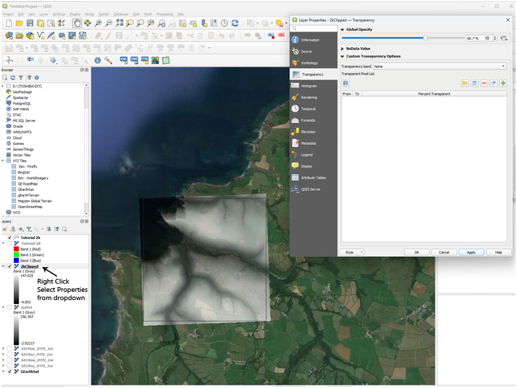
You can check the new rotation alignment of the clipped area by reducing the Opacity of the layer by right clicking the layer and Select- Properties - Transparency and adjust the transparency slider to suit (transparency will not occur until after OK is selected) and Select OK.
You will have to reset the opacity back to 100% before continuing.
Create the 2048 x 2048 16 bit Greyscale Dem
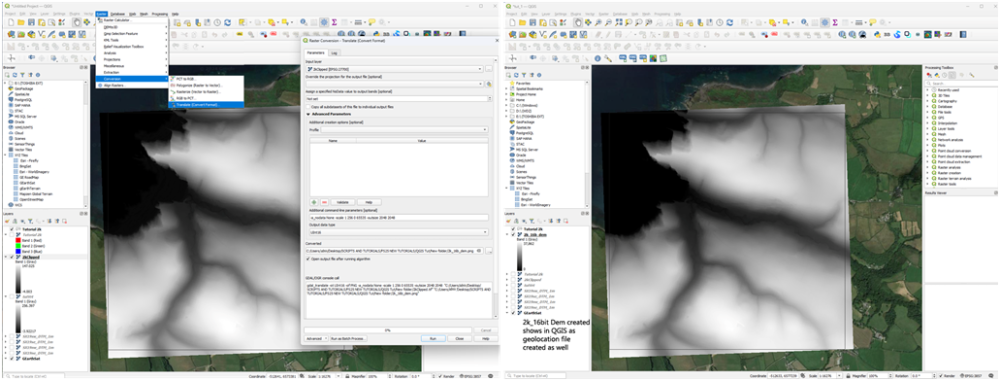
With the new 2k clipped layer selected, Select – Raster—Conversion – Translate (Convert Format)
Input Layer – Clipped 2k Area
Assign a specified No Data Value to output bands (optional) -- setting done by Additional command line parameter i.e. ‘-a_nodata None ‘
Additional command Line Parameters
-a_nodata None - This will set any blank/transparent data to black
-scale Min Max 0 65535 (Min, Max Lowest ,Highest value in the virtual Layer, 0 65535 means the whole greyscale range between 0 and 65535 will be used to represent the height values)
-outsize 2048 2048 -- this is the output image size
e.g -a_nodata None -scale 0 264 0 65535 -outsize 2048 2048 – do not forget the – at the beginning of each command else you will get Error messages
Output Data Type – Select UInt16 in the dropdown
Converted – Select icon on the far right and in the dropdown –Save to File
Browse to where you want to save the file, Name and Save as Type PNG files (*png)
This file can then be copy/pasted into your map data folder and renamed as dem.png without any further modification.
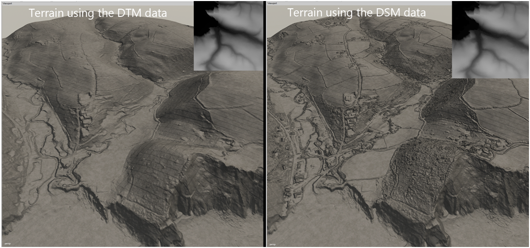
Resultant Dem images and Giants Editor images for both the DTM and DSM data
The Grid lines in the images appear to be being caused by Giants Editor 10.0.3 (don’t show with same image in GE 9.0.6)
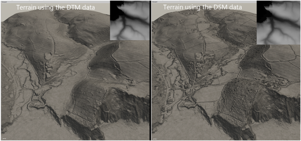
Whilst there is more detail in the DSM version it also means more smoothing/flattening of the terrain when placing items
Creating the Overlay.(Google Earth and an Image editor required)
This is just for the Google Earth overlay as in the new Giants Editor it is possible to overlay the image on to the terrain using the terrain decal setting in the Shapes Tab.
This method is for the EPSG:27700 - OSGB36/ British National Grid Lidar data -SRTM data may not require any adjustment so skip to Saving Image
Ensure Terrain is deselected in the Layers Panel
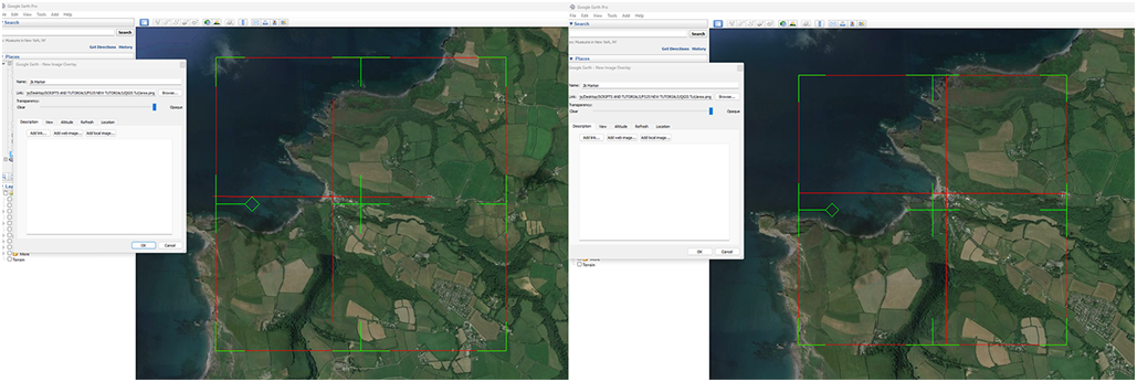
Drag drop the previously saved 2k clipped .tif into Google Earth
Select the 2k Area in the Places Panel and right click copy/paste it into the same folder rename to 2k Overlay.
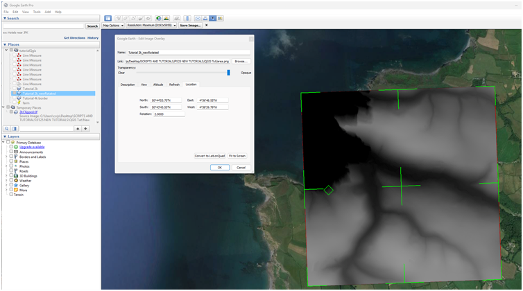
Right click the 2k Overlay and Select - Properties and adjust the rotation/alignment to match the 2k clipped.tif (I find it easier to do the rotation adjustment via the Location settings in the Google Earth –Edit Image Overlay panel which allows for finer rotation movements)
Once aligned Select- OK in the Edit Image Overlay pop up.
Marker Rotated and aligned to the 2k clipped.tif
Saving Image.
Select the Save Image Icon and zoom in to the 2k area so the marker top/bottom close to map image edges.
Deselect the 2k clipped icon in the Places Panel, if your marker has any rotation you can either adjust it in Google Earth or later in the Image Editor. (I tend to align the top marker line with the border edge)
Select - Map Options and deselect all options.
Select – Resolution Maximum and Save image in the pop up name and save in a suitable location – this will be basis for the Google Earth Satellite Overlay image.
Marker aligned to edge of Google Earth border
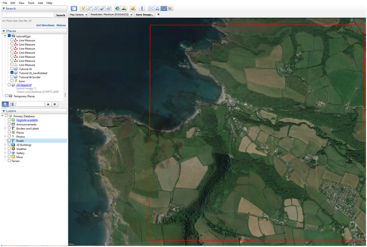
Image Editor
Any Image Editor will suffice I will be using Photoshop (crimbo present) otherwise I would still be using my free legacy version of Photoshop CS2 which does almost everything needed for Giants Editor/Farming Simulator creations with just a couple of free plugins.
https://www.techspot.com/downloads/3689-adobe-photoshop-cs2.html
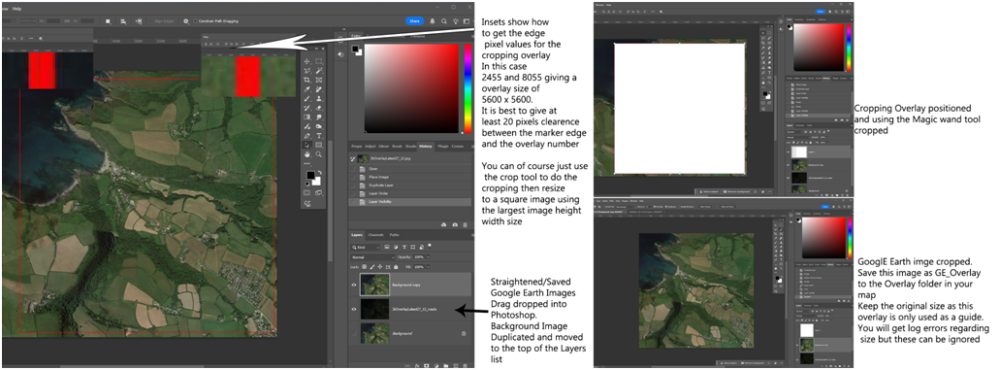
Drag/drop the Google Earth image into the image Editor
Duplicate the Google Earth image and move to the top of the Layer list, the original Background Image can now be deleted.
Cropping the image for the overlay, there are two ways of doing this
The easiest is by using the cropping tool and adjust it so it is just inside the marker edges then crop and resize the image to the largest Height/Width value.
The second is by creating an overlay that fits inside the marker and using this to crop the image, for this you will need to have the rulers set to pixels.
Zoom in to the left hand marker edge and note the pixel vale about 20 pixels from the edge of the marker do the same for the left hand marker edge subtract the lowest from the highest and create a new image of this size and fill with colour (any), copy/paste into the Google Earth image and adjust to be inside the marker edges, when satisfied select the new image with the Magic Wand tool and select Image - Crop.
Save the cropped Google Earth Layer as GE_ Overlay.png and place it in the Overlay folder (replacing original), keep the cropped size as this is just used as a guide, you will get size errors in the log but these can be ignored.
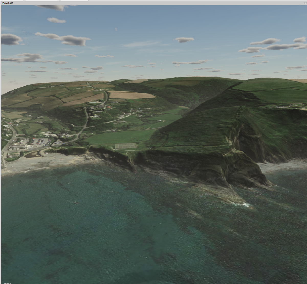
Once the Ge_Overlay.png image and dem.png are placed in their relevant folders open Giants Editor and import the overlay.i3d into the Scenegraph adjust the height of the overlay to match the terrain height, the following image shows the result (dem is the DTM version)
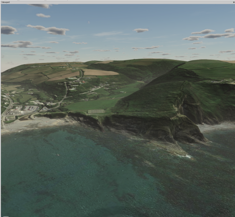
Note: The image is aligned to all the terrains 'lumps/bumps' roads/cliffs etc
Should you wish to create additional overlays/markers using dirt/grass asphalt weight textures or border meshes then please refer to the Overlays section in the DEMs and Borders the Easy Way tutorial
-
 1
1
-
-
What was his answer ?
Any log errors when running the script ?
-
Why not ask him he can be found on the giants forum site
https://forum.giants-software.com/memberlist.php?mode=viewprofile&u=60707 under the name olahaldor
or here
-
With regard to the splineSurface 'mesh' if you apply a texture to it and adjust it to any shape you want by selecting and dragging the points then in the shape tab select terrainDecal you will get the texture and shape applied to the terrain following the terrain contour, downside is the texture will be stretched.
Select Insert to create more points, Delete to remove, holding shift whilst selecting points allows you to move all the selected points in the x,z direction you chose.
So I suppose it could be used for creating defined paths/roads
I dare say others will have different methods/uses of it, it would be nice to have a bit more definite information from Giants regarding these new features of GE.
-
1
-


Tree Distributor Script
in Mapping
Posted
Check the originators Github
https://github.com/ZenJakey/fs25-scripts/tree/main