


WrinkleysRule
-
Posts
244 -
Joined
-
Last visited
-
Days Won
55
Content Type
Profiles
Gallery
Downloads
Events
Forums
Articles
Posts posted by WrinkleysRule
-
-
To get a proper dem you will need to combine all the 26 tiifs into one single tiff using a programm such as QGIS this will then even out the different shadings and gaps usually found when importing UK lidar directly into Google Earth.
The following is one combining method using QGIS
QGIS
download from here
https://qgis.org/en/site/ --approx 1.2gbOnce downloaded/installed in the folder QGIS 3.36.0 select QGIS Desktop 3.36.0
select Plugins
You now require the following plugins
Virtual Raster Builder -- may need to be reinstalled (without uninstalling) to remove error message
go2streetview
Google Earth Engine
Grass GIS provider
KML Tools
LAStools
Raster Cutter
Once you have the plugins installed Select Project -- Properties - CRS and ensure the EPSG:27700 - OSGB36/ British National Grid
is selected (tip in filter type 27700 to bring up the correct entry to select) this setting is important for alignment between the different CRS of Google and OSGB which causes the splits between rasters when imported directly into Google Earth.
Next Settings -- Rendering -- Raster -- Contrast Enhancement -- Single Band Grey --Stretch to min/Max --selected in dropdown
Drag and drop all the Defra tif images into the the main screen they will open in seperate Layers
Now select Raster -- Miscellaneous --Build Virtual Raster
At the end of the Input Layers box select the 3 dots this will bring up another pop up with a list of all the layers in your Layers panel
Select All then Run
A new Layer will appear named Virtual with all the selected Layers merged into one image with the correct brightness/contrast
To save this virtual file as a tif right click on it Export -- Save As
in the 'Save Raster Layer as' pop up
Select Rendered Image
Select the three dots at the end of the filename box to open a file browser add file name Save
and in Save Raster layer pop up select OK
Open Google Earth and drag drop new file into itNOTE: The CRS EPSG:27700 - OSGB36/British National Grid setting only applies to UK Lidar for any other SRTM Tiff the setting has to be changed to match that tiffs CRS.
-
@c.christensen98
Pm me the coordinates of your Geo. tiff (ie. n51_w003_1arc) and the site you downloaded it from and I will see what is going on with this continuing 'whiteout'.
-
@deboy130
As far as I'm aware you cannot create a 45x map all maps have to be to ^2 i.e 2,4,8,16,32 64 etc
see this list of map dem/gdm/grle sizes required for the various size maps (courtesy of Bonger76)
Normal map size
1. densityMap_fruits: 4096x4096
2. densityMap_ground: 4096x4096
3. densityMap_height: 4096x4096
4. densityMap_stones: 4096x4096
5. densityMap_weed: 4096x4096
6. infoLayer_farmland: 1024x1024
7. infoLayer_indoorMask: 4096x4096
8. infoLayer_navigationCollision: 2048x2048
9. infoLayer_placementCollisionGenerated: 1024x1024
10. infoLayer_tipCollision: 4096x4096
11. infoLayer_tipCollisionGenerated: 4096x4096
12. map_dem: 1025x1025
4x map size
1. densityMap_fruits: 8192x8192
2. densityMap_ground: 8192x8192
3. densityMap_height: 8192x8192
4. densityMap_stones: 8192x8192
5. densityMap_weed: 8192x8192
6. infoLayer_farmland: 2048x2048
7. infoLayer_indoorMask: 8192x8192
8. infoLayer_navigationCollision: 4096x4096
9. infoLayer_placementCollisionGenerated: 2048x2048
10. infoLayer_tipCollision: 8192x8192
11. infoLayer_tipCollisionGenerated: 8192x8192
12. map_dem: 2049x2049
16x map size
1. densityMap_fruits: 16384x16384
2. densityMap_ground: 16384x16384
3. densityMap_height: 16384x16384
4. densityMap_stones: 16384x16384
5. densityMap_weed: 16384x16384
6. infoLayer_farmland: 4096x4096
7. infoLayer_indoorMask: 16384x16384
8. infoLayer_navigationCollision: 8192x8192
9. infoLayer_placementCollisionGenerated: 4096x4096
10. infoLayer_tipCollision: 16384x16384
11. infoLayer_tipCollisionGenerated: 16384x16384
12. map_dem: 4097x4097 -
@c.christensen98, see the note in the Microdem section of the tutorial
Note:
Some SRTM’a display a completely white images in Google Earth, if this happens open the SRTM in Microdem and follow the above steps to modify the Display Parameters. -
-
The CSV script is primarily for use where the spline is created away from the terrain for example tracing the road layout along the Google Earth Layout image then executing the script so that the new spline follows the terrain contours and road shape.
It can also be used to crete a rough spline path with minimal CV's and then create a new spline with a chosen number of CV's for greter accuracy when setting terrain height and road layout.
-
Unfortunately there is no way to turn off the road labels but you can reduce the size of the font by Tools --Options --3D Font and selecting the smallest size and Apply.
I will add a rider to the main tutorial regarding the new method for later versions of Blender.
-
 1
1
-
-
Did you follow the new tutorial for Blender 2.93 and above on page three of this topic.
-
1
-
-
As it appears you only require the splines you would have to rewrite the script so that just the splines are created and using the multiple spline entry section from the
EditorUtils.paintTerrainBySpline script in the EditorUtils.lua (which can be found in C:/Users/YOUR COMPUTER NAME/AppData/Local/GIANTS Editor 64bit 9.0.6/scripts/EditorScripts) to allow multiple splines to be selected, though given the large number of splines (approx 500 of unknown length) I would expect it to take a fair few hours to create all the new splines notwhistanding any crashes/freezes that may/may not occur.
I may be mistaken but as far as I'm aware Autodrive only uses splines(traffic/AI) for route management not for the creation of courses. -
I stopped using microdem as I couldn't get it to work correctly with the OS CRS 27700.
I now use QGIS for any dems needed which is a fully functioning geospatial programme and allows all sorts of plugins including Google Earth/Open Street map overlays
It takes a bit of getting used to but is worth it in the end.
PM me the 1m grid references and I will merge them up into a tif and png file for you if you want
Will also PM you regarding QGIS --
-
The only way of "fixing this" is to carry on placing stones where you want them.
Bear in mind that stones added in GE (Terrain Editing -Foliage Layer Painting --Foliage Layer --stone) will be saved to the maps/data/densityMap.stones.gdm file , whereas any stones added in game (Construction Brush) will only be saved in the save game folder densityMap.stones.gdm file.
Should you wish to update the main maps/data/densityMap.stones.gdm with any new additions added in game then simply copy/paste the save game densityMap.stones.gdm file to the maps/data/ folder replacing original (renaming original to backup_densityMap.stones.gdm first to avoid any problems that may occur).
-
Have the stones been placed in that area ?
Quick way to check is to convert the densityMap.stones.gdm to a png using the grle converter v7.0.1 (available here https://gdn.giants-software.com/downloads.php)
then open it in an image editor and increase the contrast until the stones layout is visible.
-
Could you supply a GE image of the InfoLayer_farmlands.grle of your map with the Terrain Info Layer Paint Mode selected and farmlands selected in the Terrain Editing Panel Info Layer Painting, Info Layer box
Preferably of the farmland area's that appear to have not been painted by the script
-
From the help menus in GE Help --Keyboard shortcuts
Delete Delete spline control vertex Insert Insert new spline control vertex Left Previous spline control vertex Right Next spline control vertex Up or Down First spline control vertex S Stitch spline endpoints O Toggle spline open/close R Reverse spline ------------ Ctrl-L Create light -
-
A problem has ben highlighted regarding the FieldUtil.onCreate attribute set by the script, it appears sometimes GE doesn't recognise some script set User Attributes leading to problems in game
To overcome any problems I have amended the fieldsNew section of the tutorial to the following,
fieldsNew -- containing a fields transform although this will have the FieldUtil.onCreate attribute set by the script I suggest deleting the attributes and
reassigning them by Add New Attribute --Type --scriptcallback -- onCreate -- Add and in the new onCreate box enter FieldUtil.onCreate
as some times GE doesn't recognise some script set User Attributes.
This only applies to the field TG in the fieldsNew TG.The relevant entries created in this fields TG must be copy/pasted in to the gameplay –fields TG replacing originals before using in game
If just copy/pasting the individual fields TG's (i.e field01,field02 etc) into the original gameplay -- fields TG then this amendment isn't necessary as the original fields TG should have the correct format.
-
Import Placeables
This script is for those people who want to modify/edit existing maps and want to load all the placeables in taht map in one hit. However any modification/deleting of any of the loaded placeables will still require manual changes to the placeables.xml.
The script will import all the placeables listed in the placeables.xml into the map at the location set in the xml and with any User Attributes that are assigned to each placeable.
Script will only import placeables from i3ds so any placeables.xml script that does not have an i3dPath in its base.filename will not be loaded and an error message with the problem xml's filePath will be printed in the console log, error message will also be printed if the mod directory doesn't have a mod associated with that map.
Any file not loaded automatically will have to be manually added to the placeholders TG.
Limitations:
Where fences/hedges/power lines have been created using the in game construction tool and then copy pasted into the placeables.xml from a save game these will not appear in their assigned position as any editing/deletion must be carried out in game and the placeables.xml manually adjusted from a new save game.
Installation and Use
To use the script unzip the Import Placeables.zip (available at the end of this tutorial) and copy/paste the folder to the location of your
GIANTS Editor 64bit 9.0.6/scripts folder in this case it is,
C:/Users/*****/AppData/Local/GIANTS Editor 64bit 9.0.6/scripts (replacing the *** with your computer name)
Open GE and open the Script Editor , Window -- Script Editor and select Import Placables
Check and amend the following lines as necessary : -
Line 50 local gInst = "C:/Program Files (x86)/Farming Simulator 2022/" --change to your Farming Simulator 2022 Installation Path if different.
Line 52 local pathModDir = "C:/Users/ccrjs/Documents/My Games/FarmingSimulator2022/mods/" --change to your mod directory path if different.
Line 54 local placePath ={"placeables.xml","xml/placeables.xml","xmls/placeables.xml","maps/mapUS/placeables.xml"}
The 'placePath' array contains the various paths that the placeables xml can normally be found, if your placeables are in a different place/folder then add the path to the list.
When done save the script, the Script Editor can now be closed.
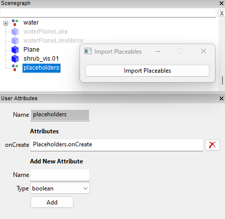
In GE create a new transform group and name it 'placeholders' with the new placeholders transform group selected, in the User Attributes Panel of GE add a new attribute Type 'script callback' with the name 'onCreate' select Add and in the new onCreate box type 'Placeholders.onCreate' (correct Font and spelling required).
This will allow the placables to be seen in GE, the new placeholders TG will be ignored when the map is opened in game and the placeables will be loaded as normal from the placeables.xml.
Select -- Scripts --Import Placeables
A pop up panel will appear with a button marked Import Placeables
Image below shows the Scenegraph and User Attributes entries together with the pop up panel
With the placeholders Transform Group selected, select the Import Placeables button.
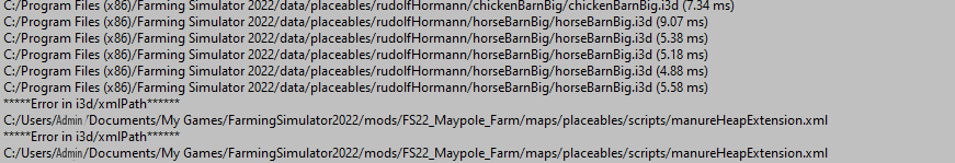
All the placeables listed in maps placeables.xml will be loaded into the map together with any User Attributes assigned and a print out of the file path to each one loaded will appear in the GE Console log.
The name of each individual placeable in the Scenegraph will be its xml/i3d name not its placeable folder name.
The script will continue running until all placeables listed (including error messages) in the placeables.xml have been loaded
An example of the console log print out showing normal and error path print outs is shown below,
I have tested the script on several maps inc
FS22_Maypole_Farm
FS22_BucksCounty
FS22_FrontierMap
FS22_Calmsden
FS22_Monette_Farms
however there maybe other maps on which the script may/may nort work as expected but I'm sure you will tell me about them.
-
 1
1
-
-
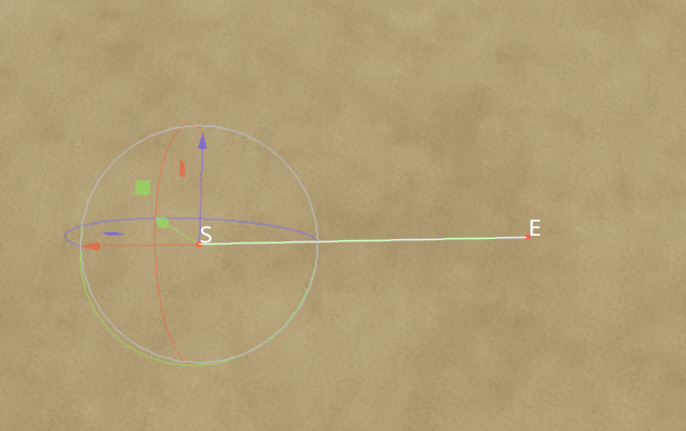
The only way I can replicate your 'problem' is to put the spline into a seperate transform group as shown below, when a spline inside a TG roup is selected it will always show the position of its parent TG as well as the spline cv's.
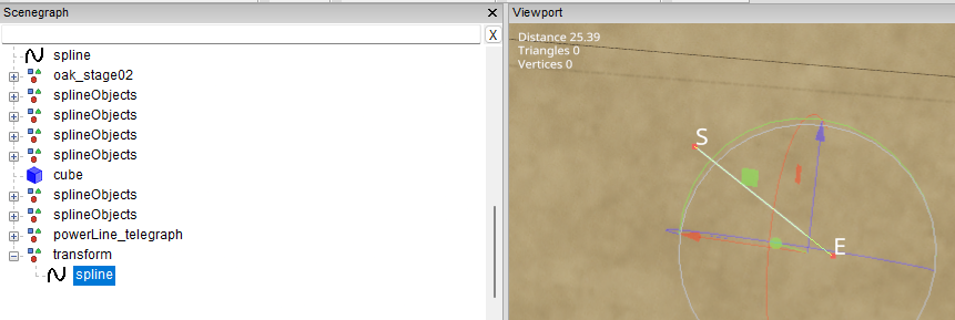
even dragging one of the points north as you suggest makes no difference as the you can still only select the 'S' or 'E' cv's not any other point
To be honest we seem to going round in circles with this and I don't have any answers (at the moment, somebody else may be able to shed light on this) to your specific problem, so all I can suggest is to start from scratch either using the default GE scripts or using the latest scripts/tutorials.
-
You do not need to put the spline in a seperate transform group (which is what you appear to be doing ) unless using the spline Placement script.
See PM for futher details
-
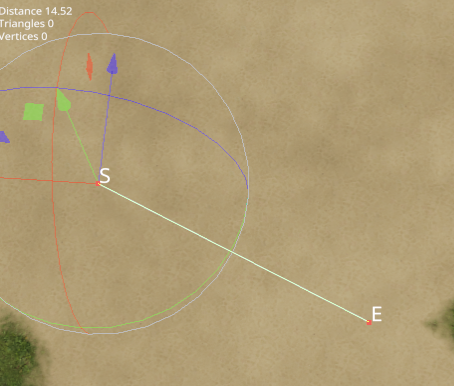
Bit confused here, if there are onlty two points on that spline I would expect to see the gizomo on either the 'E' or 'S' not in the middle.
-
If the spline hasn't been rotated and instead the S and E points have been moved to align with the first spline you will still get a distortion as the script paints along the 'X' axis and either side using the 'Z' axis
so what you have done is create a curve by moving the 'S' point down and the 'E point up.
Any deviation from the straight 'X' axiis will be seen as a curve.
One way of avoiding this is to select the 'S' cv and delete it this will move the rotation point to the centre of the spline and create a new 'S' cv so any futher adjustment is done by just the 'E' cv
-
You have rotation on the spline which is a definite no no all slpines if rotated MUST be freeze transformwed before use.
Pm is the best way if you want to discuss anything.
-
Does this only happen on corners ?
If so it could be a result of any adjustment made to the road mesh to smooth blocky curves/bends in Blender remember any changes to the mesh profile in Blender will need a change to the terrain height in GE
Also you will not be able to place the road at the exact same height as the terrain without textures flashing (hence the reason most road meshes include an edge mesh as shown in the relevant tutorial )
I believe the ingame roads have approximately 0.1 difference between the height of the terrain and the road to avoid any texture problems
-
Providing you follow the Tutorials for the each script you use, yes
"get a completely countured surface to the blender road i make, yes?"
To create a road aligned to the terrain in Blender you must first create a spline in GE and set the terrain height correctly for your road
then import the spline int o Blender and create your road from that spline.
DEM's and Borders the Easy Way
in Mapping
Posted
I am a bit confused as to what you are trying to achieve, if you want a 'farm' area of 12k x 12k then simply create a 16k x 16k map and only use the 12k x 12k section leaving the 4k surplus as a border area then if rquired add a further border mesh to get the overall 20k x 20k area you seem to want (judging by your KMZ files).