Leaderboard


Popular Content
Showing content with the highest reputation since 01/15/2019 in Posts
-
The aim of this tutorial is to create a 2k x 2k map with a 2k Border based on a 30m SRTM downloaded from opendem.info using a blank map based on the Ravenport (mapUS) . It requires a working knowledge of Google Earth, Giants Editor, Image Editors and Blender First a list of things that are required, Google Earth Image editor (Photoshop, Gimp etc) --- Paint.net not recommended as it doesn't appear to save in 8bit greyscale format only index colour Giants Editor Giants DEM Converter (modified version contained in attached Items.zip. If using original you will have to rename the image to D05_DEM.png) Snipping Tool (Windows, All programs, Accessories) Blank 2K Starter map of your choice –If using a larger map ensure the files you create are the correct size i.e. 4k map dem 2048 x 2048 weight files 4096 x 4096 Blender (Only Necessary if creating DEM Border) MicroDem (Only necessary if multiple SRTM’s required or max height difference greater than 255m) Download the Items.zip attached to the end of this tutorial which contains the Area.png and Overlay.i3d Create a new folder on the desktop and place the Items.zip file in it and unzip. NOTE:If using Felsbrunn (mapDE) as a base rename the following files upon completion of the tutorial mapUS_dem.png to mapDE_dem.png, sand04_weight.png to beachSandWet04.png If you do not want the border just ignore any reference to it in the tutorial. There are several places you can obtain SRTM’s and they range in accuracy from 90m (3 arc Second) down to 10m (1/3rd arc Second), a list of sites is below https://earthexplorer.usgs.gov/ Requires registration to download -- has the latest files and are of a better quality https://apps.nationalmap.gov/downloader/#/ USA only No log in required http://viewfinderpanoramas.org/dem3.html No log in required DOWNLOADING the SRTM OpenDem.info uses data from Copernicus and also has a list of other free DEM sites. https://opendem.info/link_dem.html No log in required To Download Select -- OpenDemEurope ---Download 1 arc-second tiles EPSG:4258 Select the OSM-WMS checkbox Zoom into the proposed area of your Farm click and drag to move the map Press and hold Control --- right click drag to form rectangle A download pop up will appear on release of mouse button Select dataset(s) (in blue text) and download. SRTM files must be in the Geo.Tiff format for this tutorial to work Pic_1 MARKING OUT the FARM and BORDER AREAS Open Google Earth ensure that the Terrain exaggeration (Tools-- Options) is set to 0.01. Zoom to your preferred location and create a 2.1k horizontal and vertical line in the shape of a cross, saving each line (the extra length of .1k is to allow for better placement later). Select the Add Image Overlay icon and browse to the location of the Area.png (from the items.zip) and open. You will now see a red square with green markers, adjust the edge markers (T shape) to fit the horizontal and vertical lines previously made this will give you a 2.1k square which you can move over the location to finalise the area by means of the centre cross or rotate using the diamond (if you move any of the corner markers you will distort the square and have to reset the edges). Once you are happy with the position click OK, rename the Untitled Image Overlay in the Places Panel to 2K Marker. If you wish to move it again right click on the 2k Marker in the Places panel and select Properties. At this point mark and name the area using the Add Placement tool as when adding the SRTM Google Earth zooms right out so the Markers may not be visible for you to centre the cursor on to crop the SRTM. Pic_2 BORDER To mark out the border all that is required is a line of 2k in length (using the Ruler Tool) leading away from each of the 2k Marker’s sides (4 in total ). Right click on the 2k Marker in the Places Panel and select copy then paste rename this to 6k Marker and adjust each side to the ends of the 4 lines as before for the 2.1k area Pic_3 CREATING the DEM’s and OVERLAY IMAGES If more than 1 SRTM is needed to cover your selected area or the min/max height difference of your area is greater than 255m you may need to use Microdem to either merge them together to ensure correct shading between SRTM’s or readjust the max/ min figures to allow proper scaling in GE. To avoid confusion here I have covered this in a separate section at the end of the tutorial. Ensure your monitor is at its highest resolution Select the Save Image Icon in the top toolbar then Map Options and deselect all items in the dropdown box, (this will remove certain text items from the image) and in the Resolution dropdown select Maximum (4706 x4800 or whatever max your monitor allows) You will require 3 images for the Border DEM and 3 for the map DEM and overlays Check that all items in the Layers Panel of Google Earth are deselected Drag and drop your SRTM directly into Google Earth At the Google Earth prompt select Crop and centre the yellow cursor over your chosen area and in the New Image Overlay box select OK Pic_4 Deselect-Reselect the 6k Marker (or just the 2k marker if not doing a border). Google Earth to Full screen and zoom in till the area marker is as large as possible and the left hand edge is aligned to the X of the Save image box If you have rotated your selection away from North South to make things easier in the image editor I suggest using the frame edge of Google Earth as guide to align the top of the 2k or 6k marker. At this stage it is advisable to create a KML file to assist with any further edits in the future, once created it will automatically open Google Earth at your location with both the area markers and SRTM (s) shown. In the places Panel deselect all the Line Measures then right click on the Temporary Places entry select Save Place As - farm name.KML to your desktop Deselect the Placement marker you created ealier As Google Earth only saves in jpg format this is fine for the Border images as jpg artifacts will not cause much of a problem whereas the Snipping Tool is better for the map dem as it can save in png format so does not suffer from any artefacts. Throughout all the following steps ensure you DO NOT move the Google Earth Image after adjustment otherwise you will have problems with alignment in the image editor For the three Border images Google Earth to Full screen and zoom in till the 6k area marker is as large as possible and the left hand edge is aligned to the X of the Save image box. Make sure the Resolution is set to Maximum (4706 x4800 or whatever max your monitor allows) With the SRTM and 6k Marker visible select save image – save as 6k_BDEM.jpg to your desktop folder (if the SRTM is visible but the 6k marker isn’t just Deselect/Reselect the 6K Marker check box). Deselect the SRTM in the Places Panel and ensure that both the 2k and 6k Markers are visible Save image – 6k¬_BMarker.jpg Deselect the 2k Marker and Save Image -- 6k_BGE.jpg Map DEM and GE, Grass, Sand and Asphalt Overlays Re Select the SRTM and 2k Marker in the Places Panel Google Earth to Full screen and zoom in till the 2k area marker is as large as possible and the left hand edge is aligned to the X of the Save Image box Using the Snipping Tool in Mode -Window Snip select new and hover the cursor over the Google Earth window and left click then File – Save as DEM.png to your desktop folder In the Places panel deselect the SRTM Using the Snipping Tool as before this time saving as GE.png In the Layers Panel select Primary Database and Roads, select the Sun icon in the top toolbar and adjust the slider for maximum darkness and again using the Snipping Tool save image as Roads.png Pic_5 Open the Image Editor (Photoshop in this case) and import all three images into it Select the DEM.png and copy/paste it into the Roads.png then do the same for the GE.png So you have an image comprising of three layers with the GE image uppermost Ensure the rulers are set to Pixels and zoom in to the left hand edge of the Area marker note the reading, do the same for the right hand edge then subtract one from the other and create a new image of that size. Copy paste this new image into the image consisting of the three layers and adjust it so that it fits inside the red area marker of the GE layer. Pic_6 Select this new layer with the Magic Wand tool and then Image –Crop The new layer can now be deleted With only the DEM layer selected Edit – Copy, File- Create New and paste the DEM image into the new image. Flatten and Resize this image to 1024 x 1024 and save it as mapUS_dem.png in your desktop folder (the DEM is resized by GE to 1025 x 1025 after saving in GE) Overlays Asphalt Returning to the original 3 layer image, the DEM layer can now be deleted. Resize the remaining image to 2048 x 2048 With only the GE layer selected Edit – Copy, File- Create New and paste the GE image into the new image Layer –Flatten Image and save as 2k_GE.png Do the same for the Roads layer and save as 2k_Roads Open the new 2k_Roads.png and select Image – Mode –Greyscale, Image –Adjustments-- Brightness/Contrast –Brightness slider full left Contrast slider full right which should leave just the road layout visible. Save this as asphalt04_weight.png Grass and Sand Open 2k_GE.png in the image editor Image --- Mode --Greyscale Filter --- Stylize -- Find Edges Image – Adjustment Brightness/Contrast adjust Contrast to a higher level (approx +50) to further enhance the edges. Image --- Adjustments --- Curves --Move both adjustments towards the centre line (Input 27 Output 0 in this case)—detail can be increased/decreased by adjusting the two points accordingly Save as sand04_weight.png Image --Adjustments -- Invert Save as grass04_weight.png Pic_7 To get the Roads to stand out more open the asphalt04_weight.png in the image editor Select Color Range and select the black area Select --Inverse Selection – and Copy Paste into grass04_weight, then (only new layer) -- Image-- Adjustments --Invert Flatten Image and resave as grass04_weight.png Do the same for the sand04_weight Pic_8 You can now try the files out by copy/pasting them into the mapUS folder and opening the map in GE then import the Overlay i3d, adjusting the Y translation of the Overlay transform group as necessary (providing you have saved the GE image as 2k_GE you should not need to alter image name/location in notepad ++). The terrain will look like a staircase and can be smoothed by using the terrain brush but a better way is to convert the mapUS_dem from 8 bit RGB to 16bit Greyscale. I have altered the cmd scripts in the DEM converter so they work on just drag and drop and not specific names like before. Copy paste the mapUS_dem into the GIANTS_DEM_Converter folder and drag/drop onto the convertTo16bitChannel.cmd file a mapUS_dem-16Bit.png will be produced. Open the new mapUS_dem-16Bit.png in the Image Editor and select Filter –Blur –Gaussian Blur –Radius 5.0 pixels and save to the mapUS folder as mapUS_dem.png. Open the map in GE and the terrain should be perfectly smooth with the height levels within 5m of what they should be when compared with Google Earth Pic_9 Pic_10 CREATING the BORDER For later versions of Blender 2.93 and above see updated Border method on page 3 of this topic Using the three images created earlier and applying the same method as for the Map DEM and GE. Open the Image Editor (Photoshop in this case) and import the 6k_BGE, 6k_BMarker and 6k_BDEM images into it Copy/Paste the 6k_BGE.jpg and 6k_BMarker into the 6k_BDEM image creating a three layer image See ---Pic_5 Above Ensure the rulers are set to Pixels and zoom in to the left hand edge of the Area marker note the reading do the same for the right hand edge then subtract one from the other and create a new image of that size. See Pic_6 Above Copy paste this new image into the image consisting of three layers and adjust it so that it fits inside the red area marker of the 6k_GE layer. Select this new layer and Image –Crop then delete new layer Resize image to 4096 x 4096 With just the DEM layer selected Select All – Copy –Create New—Paste –Flatten Image—Save as - 6k_DEM.png Do the same for the 6k_BMarker and 6k_BGE layers saving as 6k_Marker and 6k_GE respectively Blender Open Blender delete the cube ensure that the units are set to metric. Then do the following In Object mode- Add - Mesh –Planes (can also be done by adding Images as Planes but will lead to distortion and problems with scaling) Edit Mode -- Subdivide –Number of cuts 10 Add Texture – 6k_Marker.png Image Mapping --Extension --Clip U/V Unwrap Plane and assign Texture Pic_11 Object mode – Add New Texture ----add the 6k_DEM.png to the next slot with the following settings Image--Color Space to --Linear Image Mapping --Extension --Clip Mapping-- Coordinates --Generated Influence --Deselct Color Select –Intensity Pic_12 Add Modifier - Subdivision Surface -Simple - Subdivisions - View 3 Add Modifier - Displace – Texture - dropdown box select 6k_DEM texture Texture Coordinates – UV Strength – 0.1 --- set to 0.1 to allow fine adjustment when opened and aligned in Giants Editor Pic_13 Apply Subdivision Surface Modifier then Displace Modifier Add Modifier –Edge Split and apply Do not apply location or scale Export as Giants i3d as Border_1 to your desktop folder Open in Notepad++ and correct image file path. Don’t close Blender as further adjustments will be necessary Open map in GE and import the border_1.i3d Scale X =3000, Scale Z =3000 (plane 2m square border 6000m square) Y Scale this is dependant on the max height of your terrain over the whole border area (obtained from Google Earth) in this case its 281m so Y Scale equals 281 x 10 =2810 if max height below 100m then x 100 Adjust Y translation to raise lower border to fit map (may require slight adjustment to Y scale to match perfectly) Pic_14 Note where the 2k Marker is in relation to the map edges Back into Blender to delete the centre area to allow a closer match with map edges without encroaching on main map area. Edit Mode Border select –“B” and click drag to select an area 2 squares Inside the 2k Marker then ”X” to delete faces Select Edge mode Shift Alt and select one of the internal edges then lower (“G”- “Z”) by approx 2m Pic_15 Export as Giants i3d -- this time as Border.i3d Open in Notepad++ and correct image file path. Open map in GE and import the border.i3d Scale and translate as before, there should now be no incursion of the border into the main part of the map making it easier to match the edges Finally replace the 6k_Marker .png with the 6k_GE.png using the Materials Editing panel in GE To remove the shiny effect adjust the Smoothness and Metal in the Materials Editing window to 0. Finished border and DEM Pic_16 Google Earth colours obviously do not match the FS colours so a suggestion for matching the colours of the fields is to use the Distance Textures from your map files and modifying the 6k_GE.png You can also create normal and specular maps to add to the Border if you wish to make things stand out The poly count of the complete border is 15,488 in comparison the US map border/boundary has 45,836 (and only covers three sides) . MICRODEM Microdem is a freeware mapping program available from here https://www.usna.edu/Users/oceano/pguth/website/microdem/microdem.htm Ensure that all the SRTM’s you wish to merge are contained in one separate folder. If merging using Earth Explorer files ensure you have the .dt2 files i.e. n51_w003_1arc_v3.dt2 as using the normal GeoTiff.tiff file causes projection problems between Microdem and Google Earth. Open Microdem File –Open and merge DEM’s Navigate to the relevant folder select all DEM’s and open Once merged DEM’s are displayed Select – Modify –– Display Parameter -- Elevation Select zRange -- If the min/max height difference is 255m or less and max height less than or equal to 255 then the Zrange can be left as it is, for other values see Note 2 at the bottom of this section Under Display colours select Gray scale (monochrome) and click OK Pic_17 File – Save map as image – Quick map Export to Google Earth This will then open up your merged and adjusted DEM in Google Earth at the correct location. Right Click the Microdem entry in the Places Panel of Google Earth – Select – Properties and adjust the Transparency slider to Opaque and continue with the tutorial. Note: Some SRTM’a display a completely white images in Google Earth, if this happens open the SRTM in Microdem and follow the above steps to modify the Display Parameters. Note 2 Zrange Values If the difference in min/max height values is greater than 255m for example i.e 37 to 560m = 523m to keep the same ratio between the min and max heights it’s just a case of bit of maths i.e. min 37 max 560 – ratio 560/37 = 15.13 max hgt in GE 255/15.13 = 17 so new Zrange will be min 17m, max 255m If the max height is above 255 you will have to adjust the heightScale value in the map i3d to the higher value (not recommended but can be a max of 355m otherwise distortion will occur) and adjust the max height figure in the above example to suit A minimum height of 10m is advisable as GE does not allow any terraforming below 0m so no rivers or holes can be dug After adjusting the Zrange in Microdem you may find that when you check the various heights against Google Earth and in GE there will be a discrepancy in the readings this is due the different way each does its own height calculations but the difference between two points should be approximately the same i.e. Google Earth point 1. 325m, point 2. 150, GE point.1 250, point2. 75m diff between points 1 and 2= 175m. As always the final result is dependent on the quality of the original data, below is an image which shows two unedited 30m SRTM’s of this particular region. Pic_18 You can see that the Shuttle data is a lot smoother and more defined which means that it might only require converting to 16bit and not adding any Gaussian Blur factor to create a smooth terrain. Further Notes Some people have been having problems in using this tutorial so here are some helpful hints Read the tutorial carefully It requires a working knowledge of Google Earth, Giants Editor, Image Editors and Blender, there are several tutorials available on the web on these programmes if needed. Also it is based on a blank 2k map using the Ravenport (mapUS) map If using map based on the Felsbrunn (mapDE) rename the following files upon completion of the tutorial mapUS_dem.png to mapDE_dem.png, sand04_weight.png to beachSandWet04.png or beachSandRough04.png. To ensure the new weight files you create display correctly, check that all the other weight.png's in the map folder are black i.e. no texture, (white area texture created, black area no texture created). Obviously if you are using a 4k or even 16k map the Map DEM and GE, Grass, Sand and Asphalt Overlays image sizes will have to be increased by a factor of 2 i.e. 4k map 2048 x 2048 DEM, 4096 x 4096 overlays. Items.zip5 points
-
NOTE: These scripts are personal edits of original scripts by various authors ( Stegei, Evgeny Zaitsev, Nicolas Wrobel,TracMax and W_R ) and posted on the FarmerBoysModding site for members of the FarmerBoysModding community's personal use and not intended for any general public release. Furthermore they are posted on the understanding that NO monetary gain whatsoever,regardless of source can be made from all or parts of them by any person(s). Including but not limited to, Patreon, soliciting for or requiring donations for work done for any purpose, posting on a website that gives any form of remuneration per download or view. Copyright remains with the original creators of these scripts. It would appear there has been some confusion with the new and old versions of these scripts so to avoid any confusion delete any previous versions of these scripts before installing these new versions and read the New Tutorials relevant to the script you are using. 24/05/23 --- Newer versions of some of these scripts available here Installation First a big thank you to Stegei, Evgeny Zaitsev, Nicolas Wrobel and TracMax the originators of some of these scripts. Whats New All the scripts no longer require the use of the Script Editor and are now executed directly from the script dropdown in GE ,- Select--Scripts The scripts now contain a set of Set Up scripts (Spline CSV Creator Set Up, Terrain Paint Set Up, Terrain Height Set Up and Spline Placement Transform ). These have to be run before using the main script as they create in the User Attributes panel of GE the User Attributes required for each script. They only require to be run once for each spline used whilst editing, also if the map is saved between edits the User Attributes created are also saved to the spline used so the setup script does not have to be run again when the map is opened for subsequent edits. Because of the various changes/updates to all the scripts it is recommended that all previous versions be deleted before installing the new versions. Download and unzip the Updated Spline Scripts.zip, and copy/paste the contents as laid out in the zip directly into C:\Users\Your Computer name\AppData\Local\GIANTS Editor 64bit 9.0.3\scripts The Updated Spline Scripts.Zip contains the following files, a brief description of each follows, further detailed information is contained in the relevant tutorials. Spline CSV Creator Set Up Creates in Giants Editor User Attributes Panel the User Attributes for the Spline CSV Creator script. Spline CSV Creator Creates a new Spline.i3d aligned to the terrain with the CSV distance set by the CSV Distance attribute in the User Attributes panel, also created is a Spline CSV data .txt both are placed in the new CSVdata folder created in the root folder of your map. Requires Spline CSV Creator Set Up to be executed first. Terrain Paint Set Up This script prints the terrain layer textures numerically in the Giants Editor Console log. It also creates in the Giants Editor User Attributes panel the necessary User Attributes for the Terrain Paint script operation.. Terrain Paint For painting along the spline using map terrain textures, different textures can be selectedand painted for the centre and left and right edge areas. Requires Terrain Paint Set Up to be executed first. Terrain Height Set Up Creates in the User Attributes panel of Giants Editor the necessary User Attributes for the Terrain Height script Terrain Height Allows for setting the terrain height using a spline and has independent height settings for centre width, left and right edge width. Requires Terrain Height Set Up to be executed first. Spline Placement Transform Creates a splineObjects transform group with the correct hierarchy in the Giants Editor Scenegraph and in User Attributes panel the User Attributes necessary for the operation of the Spline Placement script. Spline Placement Places objects along a spline at terrain height at fixed or random distances along/around and either side of the spline Requires Spline Placement Transform to be executed first Spline Placement Delete Deletes ALL objects in the placedObjects transform group. ----------------------------------------------------------------------------------------------------------------- Giants Editor Spline Scripts User Attributes Brief description of the various User Attribute settings, further information available in the relevant tutorial. Note: If the map is saved the User Attributes created will be saved (complete with settings) to the relevant Transform Group/Object and will be available when the map is reopened, as such to avoid complications with the save if any of the individual User Attributes are deleted (by selecting the red X) then the next time any of the scripts are run a warning will be printed in the Console log, example below \ WARNING\ ATTRIBUTES ERROR PLEASE RESELECT SPLINE PLACEMENT TRANSFORM The User Attributes will then have to be set up again by reselecting the named Set Up script in the above case the error is with the Spline Placement script Spline CSV Creator script User Attributes created after selecting Scripts-- Spline CSV Creator Set Up Terrain Height script User Attributes created after selecting Scripts—Terrain Height Set Up Terrain Paint script User Attributes created after selecting Scripts—Terrain Paint Set Up The letters in brackets on the left of each Attribute name are there to ensure correct layout if more than one set of spline attributes are set up on a single spline, the script name is also entered to separate the individual Script Attributes, example below. Spline Placement script This script isn’t affected by the multiple attributes problem (shown above) although it still uses the same spline as the rest the Attributes are assigned to the splinePlacementTransform not the spline itself. User Attributes created after selecting Scripts—Spline Placement Transform To avoid errors and having to repeat the various Set Up scripts it is advisable not to delete any of the User Attributes until work has finished using the particular spline after which they can be all deleted if required. Further information available from the tutorials Export a Spline from Giants Editor Into Blender to Create Roads/Railways (Updated) Terrain Height, Paint Terrain and Spline Placement scripts (Updated) Note: Before using any of these scripts on a current Work In Progress (WIP) map, it is recommended that a blank starter map is used to experiment and get familiar with the scripts, settings, executions and results. Read the New Tutorials as the operation and execution of all the scripts has changed. Updated Spline Scripts_18.12.2022.zip5 points
-
NOTE: An updated version of the Spline CSV Creator Panels script is available here https://farmerboysmodding.com/index.php?/topic/2471-spline-csv-creator-panel-updated/ This new version creates a spline.obj file from the newly created spline for direct import into Blender without the need to convert from a .csv file This spline.obj will still need converting to a curve in Blender to create roads etc. There are two parts to this tutorial, the first part deals with creating a 2D spline in Giants Editor and using the Spline CSV Creator scripts to create a new spline aligned to the terrain with more cv's at a chosen set distance along it. Also created is a CSV (Comma Separated Variable ) file for use in Blender 2.79 (Only) to create a road mesh .i3d aligned to the map terrain. The following scripts are also used in this tutorial. Spline CSV Creator Set Up Terrain Paint Set Up, Terrain Paint Terrain Height Set Up Terrain Height The second part, the Blender section deals with creating a new mesh from the CSV data and using it to create a road layout i3d aligned to the terrain of your map for import into Giants Editor. Note: There is now an add on that imports the csv file directly into Blender see https://farmerboysmodding.com/index.php?/topic/2438-blender-plugin-300-and-above-for-splinecsv-data/ Whilst at first the tutorial may seem a little complicated once run through a couple of times it will seem quite easy. All the scripts used in this tutorial, together with the installation instructions are available here. 24/05/23 --- Link to newer versions of the scripts -- these versions do not require the separate setUp scripts https://farmerboysmodding.com/index.php?/topic/2439-new-spline-paint-height-csv-field-creationdimension-panel-scripts/ Link to original updated scripts https://farmerboysmodding.com/index.php?/topic/2412-updated-spline-csv-height-paint-place-scripts/ GIANTS EDITOR Spline CSV Creator Set Up Creates in the Giants Editor User Attributes panel the required User Attributes for the Spline CSV Creator The script is executed simply by Selecting –Scripts -- Spline CSV Creator Set Up in GE --and must be initiated before executing the Spline CSV Creator script. Spline CSV Creator Creates a new Spline_CSV.i3d from an existing spline aligned to the terrain with the CSV distance set by the CSV Distance attribute in the User Attributes panel, also created is a Spline_ CSV data .txt both are placed in the new CSVdata folder created In the root folder of your map. The CSV data is automatically converted from the Giants Editor transform axis to the Blender format, X(Z) axis, Y(X) axis, Z(Y) axis, (Giants in brackets) to use with the csv Importer script in Blender 2.79 The script allows for the original spline to be created in 2D with less cv’s and away from the terrain, the new spline created can easily be used in any of the Spline Height/Paint/ Placement scripts. Create a spline and align it to the road/rail network you wish to model, naming it accordingly. The spline can be called any name as long as it has the word spline in it i.e. road01_spline, spline_2 etc, the name chosen will also be the name of the spline.i3d and spline_CSVdata.txt created in the CSVdata folder in your map root folder. In Giants Editor --Select Scripts—Spline CSV Creator Set Up which will then create the User Attributes required by the Spline CSV Creator script a ‘ ‘SplineName’ CSV Creator Attributes Created ‘ message will appear in the consol log, then, Insert your map name in the (b).Map Name attribute The full name of your map ( root folder name) must be entered (Case Sensitive) in the (b). Map Name attribute in order for the CSVdata folder to be place in the correct position (map Root Folder) Insert the required value to the (c).CSV Distance attribute. The lower the number the more cv’s and greater accuracy in alignment in Blender or when used with the Spline Placement script In the example image below its set to 5, generally a value of 5 for roads and 10 or more for train tracks (gives a smoother incline) should be sufficient, but bear in mind that this distance will be the size of your individual road/rail sections in Blender. With the spline selected Select –Scripts --Spline CSV Creator A new Spline.i3d with your chosen Spline name will be placed in a newly created CSVdata folder in the map root folder along with a Spline_CSVdata.txt file. The message ‘New Spline: road01_spline_CSV.i3d and road01_CSVdata.txt created in Manor Farm / CSVdata Folder’ will also appear in the consol log, in this example the spline has been named road01_spline and map name is ‘Manor Farm. The new road01_spline.i3d can be imported directly into the map in GE by selecting File-Import and navigating to the map CSVdata folder in the map root folder and selecting the road01_spline_CSV.i3d which will then appear at the correct location in your map. The road01_CSVdata .txt is for use with the csv_importer script in Blender 2.79(only at the moment) and can be referenced in Blender directly from the CSVdata folder. The following image shows the Attributes and log messages created when selecting -- Spline CSV Creator Set Up Spline CSV Creator finally showing the imported road01_spline_CSV, note that the imported road01_spline_CSV translation is now set at 0,0,0 not at the road01_spline settings Setting Up the map Navigate to the CSVdata folder (in your map Root folder) and import the new --your name spline_CSV.i3d The next step is to paint the terrain along the road01_spline_CSV spline. Whilst this is not strictly necessary there are two reasons to do it, the first is to paint the terrain under any road mesh with a high AI value texture such as Asphalt or Gravel, although this probably won’t be seen, it means that an AI spline need not be created along any road mesh route not covered by the main traffic or AI splines, the second is purely for indication of road and edge size when setting the terrain height along this spline (settings should roughly reference to final Blender road width). It can also gives a performance advantage by allowing a lower clip distance on the road mesh without any visual loss when viewed from a distance. First Select—Scripts -- Terrain Paint Set Up this will create the User Attributes necessary for the Terrain Paint script and also print out the terrain layers textures in the Console log. In this example the Attributes have been sets as Set Centre Texture Width 5m Set Edge Texture Width 3m (both edges) Set Edge Texture Left 102 --see print out in Console Log for GRASS Set TextureCentre 98 --see print out in Console Log for ASPHALT Set Edge Texture Right 102 --see print out in Console Log for GRASS Set Distance Between Textures 0.5 --textures painted every 0.5m Select—Scripts-- Terrain Paint and the terrain will be painted with the chosen textures the following entry is printed out in the Console log detailing the settings. Spline Name : road01_spline _CSV Texture Left :- 93 -- GRASS Texture Centre :- 89 -- ASPHALT Texture Right :- 93 -- GRASS Centre Width : 5.0 m : Edge Width : 3.0 m : Texture Distance: 0.5 Result shown in following image. To ensure any new road mesh created using this CSV spline as a base fits the terrain it is necessary to provisionally adjust the terrain height along the length of the spline using the Terrain Height scripts. Terrain height may need to be adjusted when road mesh finally completed due to relaxing/smoothing of csv mesh. Before executing the Terrain Height script ensure that you save the map and make a backup copy of your map_dem.png in case of any problems. Select Scripts - Terrain Height Set Up This will create the necessary User Attributes used by the Terrain Height script. In the image above, the inset shows the original terrain profile with a sharp drop on the right hand side and raised terrain on the left hand side so the settings below have taken this into account this allows easier blending of either edge with GE terrain tools once the Terrain Height script has been executed. Also note that the Terrain Paint User Attributes are also shown the User Attributes window this is because the map was saved before the Terrain Height Set Up script was executed so the Terrain Paint User attributes were saved in the normal way and can still be used to adjust terrain textures using this road01_spline _CSV spline. User Attribute values, Set CentreWidth 6 (m) -- size dependant on final mesh size in Blender in this case a 6m roadbed with 2m Edges giving a 1m adjustment for final blending in GE after placement. Set SplineHeight 0 (m) --spline aligned to terrain Edge Transformation ‘selected’ --allows independent height and smoothing to either edge Set EdgeWidth 3 (m) 3m edge width either side of the CentreWidth Set Edge Height Left 4 (m) raises the left hand edge by 4m to match left hand terrain. Set Edge Height Right -4 (m) lowers right hand edge by-4m to match right hand terrain Set Edge Smooth Left 10 factors the amount of smoothing on the left hand edge Set Edge Smooth Right 10 factors the amount of smoothing on the right hand edge Select Scripts—Terrain Height The effects of these values are shown in the main window of the image above also printed in the Console log is a reference detailing the settings used together with the name of the spline, in this case Spline Name : road01_spline _CSV Offset:'True' Spline Height: 0.0 Centre Width: 7.0 m :Edge Width: 4.0 m : Height Left: 4 :Height Right: -4 : Smoothing Left: 8 Smoothing Right:8 Shown bottom right in the above image Further smoothing of the edge area can be made by reducing the EdgeWidth , HeightLeft and HeightRight by 1 and re executing the script until the EdgeWidth is ‘0’ (CentreWidth value not changed during this operation) Also note that the Terrain Paint User Attributes are also shown the User Attributes window this is because the map was saved before the Terrain Height Set Up script was executed . Note: Once executed this terrain deformation cannot normally be undone, but provided you haven’t saved the map after executing the script the terrain can be reset back to previous levels by selecting the Reload i3d in the toolbar( under the Create tab) then re adjusting script values as required. If the map has been saved then the only way of redoing the terrain is to Copy/Paste your backup map_dem.png into the map data folder. Once happy with the results save the map. NOTE: Before continuing see note at the beginning of the tutorial regarding update Spline CSV Panel script which now creates a spline.obj for direct import into BLender BLENDER 3.0.0 and above I have created a new plugin for Blender 3.0.0 and above which allows the SplineCSV data created in the Spline CSV Creator script to be directly imported into Blender instead of having to use an earlier version of Blender and exporting/importing as an obj which was previously necessary. Installation Download the spline_csv_importer.zip file available at the bottom of this topic. Open Blender (3.0.0 and above) Select –Edit—Preferences –Install and in the file browser navigate to where you saved the spline_csv_importer.zip file, Select and Install the Add-on. Once installed Activate it by selecting the check box (a single Left click usually brings up the Activation and Information panel) The Add-on can also be found in the Blender Preferences panel under Import-Export: Spline CSV Importer. Spline_CSV Importer Open Blender, Select File –Import – Import_Spline Data (*txt) a File Browser Panel will pop up. ( an undocumented operator panel appear but this can be ignored it just means I haven’t documented it with Blender) Navigate to where the CSVdata folder is (your map root folder), double click to open the folder and select the relevant spline_CSVdata.txt file, once selected, select the IMPORT CSV tab in the file browser. A new Collection in the Scene Collection Panel , SplineCSV will have been created and into that the new spline_CSVdata mesh (keeping your original name) will have been placed and the new spline_CSVdata mesh will also have been created in the same position in Blender as it was in your map ready for you to work with, the image below is for reference. All subsequent imports of Spline CSV data will be appended to the SplineCSV Collection retaining their original names Note: This Add-on will only create an single edge mesh (no other type of mesh) from a txt file created in the same format as the spline_CSVdata.txt file (i.e. no header), coordinates in the spline_CSVdata.tx have already been converted to the Blender format in the CSV Creator script and can be exported as an i3d or Nurbs curves directly back into Giants Editor. Blender 3.2 and above (other versions may differ in Menu’s and settings) Do NOT change the location of your mesh, if it is changed then problems will occur in placement when exporting final road mesh. (Quick way of getting the mesh in view is with the mesh selected, in the Collections panel, select decimal point on the Keypad) In Edit Mode ,with the mesh selected open the Tools Panel ‘N’ and select Edit – Loop Tools – Relax (arrow to left of word Relax) In the dropdown Interpolation –LinearInput Iterations ‘ 1 ‘ Note: High values will result in straightening out of curves Regular –Selected And select Relax This will relax the mesh giving a smoother line along the whole mesh. Change to Object Mode, with the mesh selected –Select , Object—Convert—Curve , this converts the mesh to a curve ready for use with the Curve Tools. Select the Curve Icon in the Scene panel (green semi circle) to open the Curve Tools Panel With the curve still selected change to Edit Mode The new curve first needs to be aligned along the correct axis for the road, to do this you can either select Control Points—Tilt and type 90 or simply (Ctrl ) -- T -- 90 In the Shape panel of the Curve Tools, select 3D, Fill Mode 'Half', Curve Deform 'Radius Selected', all other settings can be left as is. Open the Geometry and Bevel Tabs Geometry Tab Extrude ‘ 3 ‘ ---this equates to a road bed width of 6 metres , half the desired width Offset ‘ 0 ‘ ---value can be left at 0 as this just raises or lowers the mesh by +-1m Bevel Tab Select -- Profile Depth ‘ 2 ’ -- this figure is the width of the road edges in metres, in this case 2 for 2m Resoloution – ‘ 0 ’ --This figure sets the number of subdivisions in the edge mesh should you wish to create your own custom or preset profile. You will note that after entering the figure in the Depth box the curve point of origin is now aligned to the bottom of the edges, this change will need to be catered for when the mesh is finally imported into GE. The following image shows the result of these transformations. Once you are happy with the basic shape, the curve deformations can now be turned into an editable mesh. With the curve selected Object Mode – Object –Convert --- Mesh The mesh can now be edited in the normal way for example adjusting the bends in the road to be smoother and adding white lines (see Enhancements at the end of the tutorial). Texture Add the texture you are going to use in the normal way One quick method I use is in the example below, Edit mode –with all the road bed faces selected UV –Reset -- adjust the UV map to fit the road bed texture (inset 1 shows full road texture ) Do the same for each of the road edges then, Edit Mode—Edge Select – and select both outside road edges and raise to a shallower angle (inset 2) Finally Export as an i3d either using the .blend filename or creating your own in File Location Open your map in GE and import the road mesh i3d (in this case it is road01_splineCSV) Rotate the ‘Y’ axis by -90 and adjust the ‘Y’ Translation of the road mesh to match the flattened terrain. Further adjustments (texturing/terrain height) of the road area can now be carried out. The image below shows the road imported and adjusted, the inset shows a magnified image of the road placement at the indicated location. Note: To enable the AI to work better with the new road mesh, the Collision Mask (Hex) should be set up as follows, Where 0: "DEFAULT: The default bit", 1: "STATIC_WORLD: Collision with terrain, terrainHeight and static objects", 2: "STATIC_WORLD_WITHOUT_DELTA: Deprecated in FS22: Do not use it anymore!", 3: "STATIC_OBJECTS: Collision with static objects", 4: "STATIC_OBJECT: A static object", Deselected is 5: "AI_BLOCKING: Blocks the AI", 6: "TRACTOR: Deprecated in FS22: Do not use it anymore!", 7: "COMBINE: Deprecated in FS22: Do not use it anymore!", 18: "AI_DRIVABLE: AI can drive over this node", The above settings are taken from the base game road mesh , although numbers 2,6, and 7 state that they are no longer used it would be prudent to include them anyway as the collision masks may have changed in later game patches. ENHANCEMENTS Adjusting and smoothing blocky curves/bends Example; Navigate to a curve section you want to adjust in the viewport Edit Mode Select the outer edges of the road sections in the bend (3 in this case) and subdivide, number of subdivisions will be dependent on smoothness required. Open the Tools Panel ‘N’ and select Edit – Loop Tools – Relax (arrow to left of word Relax) In the dropdown Interpolation –Linear- Projects vertices on straight line, Cubic uses a natural cubic spline to project the vertices Input – Parallel (all) --This will also modify any parallel vertices at the same time, if in doubt select, Section, only selected modified. Iterations ‘ 1 ‘ – No of times tool is run, higher number gives smoother results but straightens out the curve Regular –Selected –When selected vertices spread evenly along the loop Select the vertices along the edge of the curve Section, and select Relax Further smoothing can be carried out by repeating the above process on the relevant section Finally select all the vertices along one edge of the whole road mesh and then select Relax This will smooth out the whole road mesh Image below shows the various stages and images 1 and 3 show the before and after result. Adding Custom road markings. Select all the road bed faces (Shift-Alt held - select face) of your finished road mesh, change to Edge select, again with Shift-Alt held deselect left and right hand edges and Subdivide ' 1 '. Select the new centre edge (Shift-Alt held - select edge) and Shift-D to copy ' P ' Selection to separate from main road mesh, with the new edge mesh selected Object mode – Object--Convert--Curve Curve Tools panel --Shape-- Geometry and set Extrude to ‘ 0.2 ‘ (Extrude value dependent on the width of the road marking texture used) Edit mode Ctrl 'T ' -90 to correct the axis. Object mode -- Object--Convert--Mesh Add texture as normal not forgetting alpha channel settings in Blender Edit mode -Face select --select all UV—Reset -- adjust UV mesh to fit texture Texture may need to be adjust on the bends but that is easily done in the UV editing window Finally when satisfied export as i3d. To do the edge markings (if required), select the left hand or right hand edge and Shift-D to copy ' P ' Selection to separate from main road mesh and continue as above, doing the same for the other edge. Example below The previous tutorial showed two ways of creating the road mesh from the CSV mesh but I think the above method is the quickest and easiest way to get the best results. As it is possible to create a spline in Blender 3.2 and export it as an i3d you can create a set of splines aligned to the road mesh to use in the Spline Placement script and also for traffic/railway splines Using the finished road mesh as an example For Spline Placement In Edit mode, Edge Select Shift-Alt select the left or right hand road edge so all the edges are selected. Shift ‘ D ‘ to copy With the edge still selected ‘ P ‘ Selection to separate Object Mode With the edge selected -- Object –Convert—Curve Edit Mode Curve –Set Spline Type – NURBS Object mode Open i3d exporter Export Tab and ensure that Nurbs Curves and Shapes are selected Set up filename and File Location in the Output tab Export the i3d Import into map set ‘ Y ‘ rotation to -90 and Edit-- Freeze Transformation –Rotate Only (leave preserve instances selected) height settings do not matter as objects will be placed on the terrain at their point of origin. Replace any splines in the splinePlacement transform with this new spline and set up the script parameters accordingly. Example before selecting Object mode and exporting For traffic/railway splines Select all the road bed faces (Shift-Alt held - select face) of your finished road mesh, change to Edge select, again with Shift-Alt held deselect left and right hand edges and Subdivide '3 '. If creating a railroad spline then Subdivide ' 1 ' Subdivide ‘ 3’ is necessary to get the correct location for the traffic splines (midway between centre and edge). The centre edge line can be used, if required, as a new roadSpline01_CSV to adjust any terrain height after smoothing of road mesh (slight straightening of bends etc). Shift-Alt select edge to the left of the centre of the road mesh so all the edges are selected and continue as above for the splineUtilsPlace adding a further step after the ‘With the edge still selected ‘ P ‘ Selection to separate’ of renaming the mesh to traffic01_left for clarity and continue the method above. Repeat the procedure for the right hand edge. Image showing both sets of splines. Once the traffic splines are imported the Translation/Rotation needs to be set up as follows Translate ‘ X ‘ and ‘ Z ‘ to‘ 0 ‘ Translate ‘Y ‘ to a suitable value to align it just above the road mesh, in this case -1.9 Rotate ‘ X ‘ and ‘ Z ‘ to ‘ 0 ‘ Rotate ‘Y ‘ to -90 Once done freeze (Edit-Freeze Transformation) the Transformation/Rotation settings. As both traffic splines, after importing are in the same direction, traffic direction can be set by selecting the relevant spline and pressing the ‘ R ‘ key on your keyboard. All the splines once imported into the map can be edited/ expanded in the normal way. Note: Regardless of the filename you have given the spline in Blender the name in the scenegraph of GE will be the name in the Collections Panel of Blender with the suffix.001 in this case road01_splineCSV.001 Below is an example showing the road mesh, markings, together with the various splines and also objects that have been placed using the Spline Placement script (see Terrain Height, Paint Terrain and Spline Placement scripts (Updated) for details of placement). spline_csv_importer.zip4 points
-
This script can be used to easily place fences/power lines on a map using a spline. It consists of a basic spline placement script and a modified easyFence script (by modelleicher) combined with some extra enhancements. The script works by first placing posts/poles aligned to the terrain along a spline, it then places fence boards/wires on these posts/poles scaling them to match the distance to the next post/pole. To install download the script (available at the end of this tutorial) unzip the fencePowerPlacement.zip and Copy/Paste the script into C:\Users\Your Computer Name\AppData\Local\GIANTS Editor 64bit 9.0.4\scripts. Once installed, to initiate the script select the Fence Power Placement script in the GE Scripts tab. A panel will pop up somewhere on the screen. The image below shows the Panel, together with a brief description of the Inputs/Parameters Points to Note before using this script. All posts/poles/wires/boards Must be scaled at 0,0,0 before use in the script Items to be placed Must be aligned along their ‘Z’ axis with the point of origin at one end. Number of Wire/Board alignment nodes Must be the same on all posts/poles used and in the same order top to bottom otherwise you will have crossovers between the posts. The post/pole transform group hierarchy must always start with the post mesh followed by the wire/board alignment nodes it can then be followed by any other meshes although I think best practice would be to have a single mesh for the pole/post including all the parts. The following image shows the transform group hierarchy and the telegraphPost placed using the script Above Telegraph pole taken from the FS19_telegraph pole kit by Robbie available on modhub Placing a Simple Fence Simple post, fence board creation For this example I will create a simple post/board using the Create- Primitive - Cube in GE The finished fence will consist of square posts and three fence boards If you already have a suitably aligned post and fence board then skip the next section, import post and fence wire/board into GE and go to Adding the alignment nodes to a post. section. If not continue with the following, In GE Create - Primitive - cube In the attributes panel Translate 'Y' enter 0.5 also rename this post_1 Select Edit - Freeze Transformations and select Translate - this will move the cubes point of origin to the base of the cube In the attributes panel enter the following into the Scale transforms 'X' 0.15 , ‘Y’ 1.5, 'Z' 0.15 and Freeze transformation Scale (only Scale ensure all others boxes are deselected) In the material panel in Albedo Colour enter 0.4, 0.2, 0.2 this will give a brownish colour to the post Create a second cube In the attributes panel Translate 'Z' enter 0.5 and rename this to board_1. Select Edit - Freeze Transformations and select Translate - this will move the cubes point of origin to edge of the cube In the attributes panel enter the following into the Scale transforms Scale 'X' 0.1, 'Y 0.2 'Z' 4 and Freeze Transformation Scale (only Scale ensure all others boxes are deselected) Because this second cube still uses the material name ‘Unnamed material’ it will be the same colour as the post. Create a new transform group and name this fencePowerItems Select post_1 with the middle mouse button and keeping the middle mouse button pressed move post_1 into the fencePowerItems transform group, do the same with board_1. The reason for this is to keep the transforms all set to 0,0,0, which will prevent any unseen conflicts with translation positions. With the fencePowerItems transform selected on the keyboard select Ctrl B to place it in your current view port for reference. Adding the alignment nodes to a post. Create a new transform group –Create – Transform Group Select the new transform group with the middle mouse button and keeping the middle mouse button pressed move the new transform group into the post_1 transform. If you do not have a middle mouse button then cut/paste the new transform into the post transform. Next move the new transform up to where you want the lowest board to be With the new transform selected on the keyboard select Ctrl D to duplicate then move this second transform to the centre board position, repeat this step for the third transform placing it where the top board will be. Your post_1 alignment transforms should look like the post in the alignment image above. Your post transform should look like the following image Open your map in GE Create a spline – Create- Spline rename to spline_1 and align it along the route you want to place your fence. Select Scripts – Fence Power placement to initiate the script. In the Scenegraph a new transform group ‘fence_powerObjects’ will have been created consisting of three transform groups wire_fenceNode – place the fence board(s), wire(s) in this transform group fencePlacement Transform Group postObject – place your post(s)/ pole(s) in this group placedObjects – your complete fence/power line will be placed in this group when the script has been executed (select Create Fence/Power Line) The spline has to be placed in the fencePlacement Transform Group For those familiar with the original Spline Placement script this fencePlacement Transform Group works in the same way as the Spline Placement script. I have renamed the post_1 and board_1 meshes to post1S1,board_1S1 (S1 being spline_1) respectively. Unfortunately GE will scale all objects of the same name throughout the map so I have done this so that I can easily freeze the scale transformations on the completed fence/power line without affecting any other mesh in the map. Copy/Paste board_1 into the wire_fenceNode transform (rename if you want to). Copy/Paste post_1 into the postObject transform. (rename if you want to). Cut/Paste the spline into the fencePlacement transform Set Post Distance – 4 – posts will be set 4m apart Stay Upright – Selected – this will ensure the posts remain upright regardless of terrain contour Select Random Spline Order – Deselected – this will be used in a later section of the tutorial Select Random Wire/Board Placement – Deselected -- this will be used in a later section of the tutorial No of Wire/Board Nodes – 3 – this is the number of transform nodes on the post Maximum Posts – 0 – Default setting means all post will be used Start Post – 0 – default setting script will start at first post Remove Current Fence/Power Placement – Deselected With the fencePlacement transform Selected, Select the Create Fence/ Power Line button The fencePlacement transform must be selected for the script to run. In following image ‘Image 1’ shows the renamed post_1 and board_1 in their correct transform groups together with the spline in its correct position and the Fence/Power Placement Panel ready for input. Image 2 shows the Fence/Power Placement Panel with all the relevant data entered and the script executed by selecting Create Fence/ Power Line button Image 3 shows another view of the placed fence and the two other insets shoe the difference between Selecting/Deselecting the Stay Upright parameter You can check out the difference between the Stay Upright modes by, Remove Current Fence/Power Placement –Select – this will delete the current fence placement Stay Upright – Deselected Remove Current Fence/Power Placement –Deselect – Important step otherwise new placement will not take place Select -- Create Fence/ Power Line button – this will create the same fence placement but with the posts following the terrain contour To return to the original placement, Remove Current Fence/Power Placement –Select Stay Upright – Selected Remove Current Fence/Power Placement –Deselect – Important step otherwise new placement will not take place Select -- Create Fence/ Power Line button The Remove Current Fence/Power Placement selection can be used to delete an existing placement and add/change any parameter then execute the script with the new settings. For wire placement the alignment method is slightly different in that the transform nodes are placed on the outside of the post on the ‘X’ face. Although normally a fence post created for wire would already have the staples (the staples would have to be on the ‘X’ face of the post) as an integral part of the post mesh. Random Post/Board Placement For this example I have created a shiny round post by, Create – Primitive – Cylinder Rename – post_2 Translate ‘Y’ – 0.5 Freeze Transform Translate Scale X 0.2, Y 2, Z 0.2 Freeze Transform Scale Albedo Color 0.8,0.8,0.8, Smoothness 1 Metalness 1 Cut Paste into fencePowerItems Transform For the boards I have just duplicated board_1 twice renamed board _2, board _3 respectively and scaled X,Y values (not Z as this is the distance between posts) then Freeze Transformed scale on the new boards Ctrl B the new fencePower Items to your map location The alignment nodes on the post are set up the same way as for the post_1 (must be the same number) Copy/Paste board_2,3 into wire_fenceNodes Copy/Paste post_2 – into the postObject transform Using the same spline the script set up is as follows Set Post Distance – 4 – posts will be set 4m apart Stay Upright – Selected Select Random Spline Order –Selected Select Random Wire/Board Placement – Selected No of Wire/Board Nodes – 3 – this is the number of transform nodes on the post Maximum Posts – 0 – Default setting means all post will be used Start Post – 0 – default setting script will start at first post Remove Current Fence/Power Placement – Deselected With the fencePlacement transform Selected, Select the Create Fence/ Power Line button The image below shows the Script parameters and random placement of both the posts and boards If you want to create some missing fence boards add another empty transform group to the wire_FenceNode transform group. The odd posts are deliberate to highlight the effect of the random spline placement Power Lines I will be using some premade power pole and wires for this example An example of a power pole with multiple objects is shown in the Points to Note before using this script section at the beginning of this tutorial The alignment node set up method is slightly different for the power poles. Create a transform group and Select the new transform group with the middle mouse button and keeping the middle mouse button pressed move the new transform group into the powerPole transform group. With the new transform node selected, hover the mouse over the insulator you want to hold one of the wires, then Ctrl B left click twice to place it on the insulator Do the same for all the other insulators Image below shows the placement of Power Lines together with the relevant script settings, inset gives a clearer picture of the placement Below Power Placement using the Select Random Wire/Board Placement with an extra saggy wire (wireSag2) randomly placed again inset shows clearer placement Finally using the script twice to place power Lines and a damaged barbed wire fence Further Notes Wire_FenceNode objects must be single meshes and not part of any transform group. There is no limit on the no of items that can be placed in either the wire_FenceNode or the postObject node the only stipulation on extra posts is that they must all have the same number of alignment nodes. Post/poles must also be single meshes and not part of any transform group. The alignment nodes on any post/pole must be the first children of that mesh, however other meshes can be placed after the alignment nodes for example Though currently if using a tree it will only be placed in one rotation and LOD1 is not supported. You can of course manually place a tree in place of a post by first selecting the post in the viewport and then in the scenegraph copy the three transform nodes of that post. Using the replace function select the post as the Target and the tree in the Replace With section and select Replace, align the tree with the end of the previous posts wires and with the tree transform group selected paste the original 3 transform copied previously into it The following image shows the result of this method Error Messages Error messages will appear in the console log if, Nothing is in the wire_FenceNode transform group Nothing is in the postObjects transform group Incorrect number of transform alignment nodes on a postObject item error message and name object will be printed in the log Spline is in the wrong transform group or not present in the fencePlacement transform Group When the script has finished the following will be printed in the log Finished! Enjoy the fence 🙂 Spline Name: (name of spline) As normal I suggest you try this script out on a test map before using on any WIP map also this script is still being developed so may change at a later date. Original Easy Fence script available here select all and paste into new notepad++ file and save as easyFence.lua. https://pastebin.com/1DR6qDcE Damaged barbed wire/poles taken from FS 19 Barbed wire fence kit by Robbie https://www.farming-simulator.com/mod.php?mod_id=105801 Fence_Power_Placement.zip3 points
-
Shywizard did this awesome video, I wanted to be sure to share it here so he doesn't have to use his personal file space. 2020-12-07_18-38-39.mp43 points
-
Create Field Dimensions and Farmlands Tutorial This tutorial will endeavour to show you how to create field dimensions, paint the farmland area (InfoLayer_farmlands.grle) and automatically add the relevant farmland entries in the farmland.xml together with painting your chosen Ground Type (i.e Plowed,Cultivated etc) and painting foliage at a chosen growing state on the chosen field using custom scripts. For clarity the abbreviation TG will be used to denote a Transform Group throughout this tutorial. I would like to thank Modelleicher for allowing me to use and giving permission to slightly modify the following scripts in this tutorial in order to add some extra functions. Create Field Dimension Panel Creates field dimensions from markers Paint_Farmland_Field_ID_Panel Paints the InfoLayer farmlands.grle and adds relevant data to the farmlands.xml. Paint Field Ground Foliage Panel Paints the chosen Ground Type (i.e.Plowed,Cultivated etc) and Foliage at a chosen state (i.e. wheat, harvest ready). All scripts are available in the Field Dimensions and Farmlands zip file available at the end of the tutorial. Also have a look at the following youTube videos by Modelleicher on the creation of the original scripts and for a master class on script creation. https://www.youtube.com/watch?v=jLL7x064mJc --Field Dimensions https://www.youtube.com/watch?v=QhCOBkOxjPE –Paint Farmlands https://www.youtube.com/watch?v=dxnZI8C02NY --Farmlands.xml Create Field Dimensions, Create Farmlands and Paint Ground and Foliage on the field The three scripts used for this are the Create Field Dimension Panel, Create Farmlands Panel and the Paint Field Ground Foliage Panel. The Paint Field Ground Foliage Panel script now automatically reads the Foliage Type, Ground Type, Ground Angle, Spray Type associated with your map from the map.i3d and displays it in a dropdown selection. However the Foliage State for each Foliage Type still requires a number value (position in the Layer State dropdown in GE) To assist with this the script now reads all the Foliage States of each Foliage Type directly from the maps foliage folder xml’s and prints result to the console log and to a foliage_States.txt file in the same folder as the map.i3d for easy reference, the image below shows the extracts from console log print out and the foliage_States.txt file . The foliage states listed here are from a test map based on the US map so yours may differ depending on your map set up. Open your map in Giants Editor and Select –Scripts, select the Field Dimensions and Farmlands folder to open it and then select the Create Field Dimension Panel script a popup Panel will appear on your screen. A new transform Group will automatically have been created in the Scenegraph called Field_Creation_Transform consisting of the following TG groups newFieldMarkers – this TG will be the the reference point for the fieldMapIndicator and also contains the Markers transform where the markers are placed. fieldsNew -- containing a fields transform although this will have the FieldUtil.onCreate attribute set by the script I suggest deleting the attributes and reassigning them by Add New Attribute --Type --scriptcallback -- onCreate -- Add and in the new onCreate box enter FieldUtil.onCreate as some times GE doesn't recognise some script set User Attributes. This only applies to the field TG in the fieldsNew TG. The relevant entries created in this fields TG must be copy/pasted in to the gameplay –fields TG replacing originals before using in game farmlandDimensions -- containing a fields TG with the FieldUtil.onCreate attribute set. This will be used in the creation of the farmlandsDimensions Create a primitive (Create –Primitives, I will be using a cone throughout this tutorial.) and cut/paste into the newFieldMarkers transform (this will be the position of your fieldMapIndicator in the new fields TG). Copy/paste a cone into the Markers TG Your Scenegraph should now look like this. If you haven’t already got an outline of your proposed field area then I suggest you make one using the Terrain Detail Texture Mode and a suitable texture. Once you have a field border then CTRL ‘B’ the newFieldMarkers transform into the field area. Note: The newFieldMarkers transform MUST be placed in a position that allows ALL the field boundary to be seen from that position (the cone in the newFieldMarkers TG will provide a reference point) otherwise the script will not work correctly, so for complicated field shapes you will have to create the fieldDimensions manually or by using FieldDimensionsWithBitmap script available from here https://ls-modcompany.com/forum/thread/5852-fs19-ge-script-fielddimensions-per-bitmap/ Also the Markers (cones) must be in a consecutive order, so if you have to add any additional markers to your layout (after creating one) then the extra marker must be placed in between existing ones in the Markers TG as the script uses each marker in turn to create the field Dimensions. Place the ‘cones’ along the edge of the field by CTRL ‘D’ (copy existing cone)-CTRL ‘B’ (place new cone) at suitable points as shown in the following image ( I have scaled the cones up for better definition). Using the fields transform in the fieldsNew TG to create the new field dimensions. In the Enter Field Number box enter the field number you want for this field. Now, first selecting the fields transform and holding Ctrl key select the Markers transform, releasing the Ctrl key and select the Create Field Dimension button. The new field dimensions together with the fieldMapIndicator will be created in the fields TG in the fieldsNew TG, if they are not visible in GE then with the fields TG selected Select – Scripts – Map –Toggle Render Field Areas and they should appear in GE. A Created Field Dimension for Field ‘field01’ message will also appear in the console log (field number will change to field created in subsequent operations). Results shown in following image. The script sets the default for fieldGrassMissions and fieldMissionAllowed to false. To change this to your prefered setting select the field number transform (field01 in the folowing image) And select the relevant box as shown below. fieldAngle can be left at 0, fieldDimensionIindex and nameIndicatorIndex refers to their position in the field(01) transform group 0 and 1 respectively. Painting the Field and adding details to farmlands.xml There are some tasks and settings to be done before this can be carried out. Firstly if you are starting from scratch then I suggest you ’Wipe’ the infoLayer_farmlands.grle if you already have fields painted then skip this next step. ‘Wipe’ infoLayer_farmlands.xml In GE zoom out until the whole map area (I use a pda camera for this ) is in view select the Terrain info Layer Paint Mode and in the Info Layer Painting panel select farmland in the drop down, select all the info channels (1-7). In the Terrain Editing Brush panel set a radius of 1000 and Brush Type square, paint the whole map area (ensure it is completely covered otherwise you will get errors in the log) and save the map. farmlands.xml If you have renamed your farmlands .xml then obviously use that name in the following and check the note in the Create Farmlands section regarding filePaths. Navigate to where the map.xml is located in your map normally Map Name/maps/mapUS (orFR/alpine) And open this in notepad++ and locate the <farmlands filename entry in this case it is <farmlands filename="$data/maps/mapUS/farmlands.xml" /> Change this to <farmlands filename="maps/mapUS/farmlands.xml" /> if you want to keep your farmlands.xml in the default position However I am going to put my farmlands.xml in a separate xml folder so my <farmlands filename entry will look like this <farmlands filename="maps/mapUS/xml/farmlands.xml" /> with the farmlands.xml placed in the new xml folder. Save the maps.xml. Open the farmlands.xml in notepad++ and ensure the path to the infoLayer_farmland.grle is correct the densityMapFilename should read densityMapFilename="maps/mapUS/data/infoLayer_farmland.grle" If you are starting from scratch open farmlands.xml and delete all the farmland entries like so. However if you already have fields created in the farmlands.xml then only delete any entries that have not yet been created leaving only the created ones e.g A second set of field Dimensions now need to be created in the fieldDimensions TG using the original set of markers. Select each of the field border markers in turn and move them to the outside of the field boundary (or if you have two fields that you want to have as one farmalnd area, to the outside of the whole area) Remember if you add any new markers the extra marker must be placed in between existing ones in the Markers TG as the script uses each marker in turn to create the field Dimensions. Once done first select the fields transform in the fieldDimensions TG and holding the Ctrl key select the Markers TG release the Ctrl key and select the Create Field Dimension button. Note: the field number is left as 1 in the Create Field Dimension script because this is the field number to be painted. Create Farmlands To paint the field infoLayer_farmland_grle and create the correct entries in the farmlands.xml in Giants Editor Select –Scripts, select the Field Dimensions and Farmlands folder to open it and then select the Create Farmlands Panel script, a popup Panel will appear on your screen. Set Land Price Scale- Enter your chosen price scale multiplier default is 1 Set NPC Area- Enter your chosen NPC area "ALPINE", "US" or "FR" Number of Different NPC’s Number of different NPC's (found in base maps npc.xml normally default 15) The npc number is randomly selected between 1 and the npcCount value in the script. Show on Farmlands Screen Default is true --false will stop field being shown on farmlands screen i.e showOnFarmlandsScreen="false" /> <!-- BGA, farmland bought via placeable --> When true the game scripts automatically show the farmlands so no showOnFarmlandsScreen entry will appear in the farmlands.xml Default Farm Property Default is false --true assigns ownership of field to player farm i.e defaultFarmProperty="true" /> Once you have made the relevant settings in the Panel , with the field01 TG (farmlandDimensions – fields - field01) selected, select the Create Farmlands button. Note: If your map has a non standard heiarchy or extra custom NPC characters then you will need to adjust some variables in the script, obviously if the map is a standard layout then this section can be ignored. The variables to change are, local farmLPath = {"farmlands.xml","xml/farmlands.xml"} – these are the normal places where the farmlands.xml is found. The script will automatically search for the xml in the following locations Main map folder Main Map/maps folder Main Map/maps/mapUS (orAlpine,FR) folder If your farmlands.xml has another name or placed in a different folder location then add this to the ‘farmLPath array ‘ not forgetting the quotes. local areas ={"ALPINE","US","FR"} – If you have another set of custom characters at a different location then add this to the ‘areas’ array again not forgetting the quotes. local npcCount = 15 -- If you have more custom characters then increase this number to the new amount. To carry out any of the above changes open the script in the GE Script Editor Window – Script Editor -- Field Dimensions and Farmlands - Create Farmlands Panel At the top of the script (lines 12,13,14) you will find these variables, adjust as necessary and save the script. The Script Editor can now be closed as it is no longer needed and the script is ready for use. The image below shows the resultant farmland painted (in Brown) with the farmlandDimensions overlayed in green. The inset shows the same farmland but selecting Farmland 1 in the Lands dropdown and show unmasked selected (removes the background colour) A INFO : Farmland id 1 Painted and farmlands.xml entry created message will also appear in the console log (field Id will change to any new Id created for subsequent fields). Note: Colours will vary as the Toggle Render Field Areas script randomly assigns colours to fields And the new entry in the farmlands.xml showing field 1 as belonging to the farm. You can create the fields in any order the script will adjust the farmlands.xml numerical order automaticaly and insert the next number in the appropriate place replacing the <farmland/> with the new field entry as shown below. If you try to create/paint a field ID that already exists then a warning will appear in the Console panel window and the existing farmland ID will not be overwritten , for example, +++++++++++++++++++++++++ Farmland ID 25 already exists in farmlands.xml Delete farmland Id 25 in the farmlands.xml if you wish to create a new farmland at Id 25 +++++++++++++++++++++++++ Should you wish to increase/decrease the size of the painted farmland area then in GE with the Terrain Layer Info Paint Mode selected and the farmland selected in the drop down in the Info Layer Painting Panel With the cursor over the area you wish to change select Ctrl ‘R’ on the keyboard and the correct farmland entry will appear in the Info Layer Painting Panel ready for you to paint Once happy save the map (sets the infolayer_farmland.grle) Painting Field Ground Type and Foliage This requires the Paint Field Ground Foliage Panel script. The script requires the correct Farming Simulator 2022 installation path, it uses a default path of "C:/Program Files (x86)/Farming Simulator 2022/". If your installation path is different then open the script in the GE Script Editor Window – Script Editor -- Field Dimensions and Farmlands - Paint Field Ground Foliage Panel At the top of the script at line 24 there is the following local gInst = "C:/Program Files (x86)/Farming Simulator 2022/" replace the "C:/Program Files (x86)/Farming Simulator 2022/" with your file path (including the quotes) and save the script. The Script Editor can now be closed as it is no longer needed and the script is ready for use. This script uses the created field dimensions to allow the painting of the Ground Type and Foliage to the field dimension area With the map open in GE select Scripts select the Field Dimensions and Farmlands folder then the Paint Field Ground Foliage Panel script the following pop up panel will appear on your screen Set Foliage Layer Select the Set Foliage Layer box and a dropdown will open listing all the various foliage layers in your map for example 'terrainDetail' Set Foliage State Only applies if terrainDetail not selected in the Set Foliage Layer. The number entered corresponds to the position of your chosen foliage state in the Layer State dropdown in the Foliage Layer Painting Panel of GE. To assist with finding the relevant foliage state all the foliage states for each ‘crop’ are printed in the console log and also in a foliage_states.txt file in the map.i3d folder Ground Type Selected from the Ground Type dropdown (all available terrain detail ground type’s listed). Ground Angle-Degrees Selected from the Ground Angle-Degrees dropdown (all available ground angles listed). Spray Types Selected from the Spray Type dropdown (all available spray types listed) Paint Ground/Foliage Executes the script Once you have entered your chosen settings with the field TG (i.e. field01) selected, select the Paint Ground/Foliage button Note: the Spray type works the same as if painted in GE so you will still get the requires lime/etc in the in game field info gui. The images below show console log print out for foliage states and the Paint Field Ground Foliage Panel settings for, Set Foliage Layer --terrain detail, Ground Type Ridge, Ground Angle -90,Spray Type Manure. Set Foliage Layer- potato, Foliage State - 5 (green big) Ground Type/GroundAngle/Spray Type left as previous as they have no effect if terrainDetail not selected. To erase/change any option select the foliage layer you want to change and either deselect it (blank) to remove or choose another foliage type , the same applies to the other options. For example selecting terraindetail and deselecting (blank) in the other setting(s) to be erased and selecting the Paint Ground/Foliage button will revert the field to the original ground texture ( in this case ‘dirt’) To remove foliage , select that foliage in the Set Foliage Layer dropdown and enter ‘0’ in the Foliage State select the Paint Ground/Foliage button will remove all the foliage of that selected Foliage Layer The script will work on any TG that has field dimensions so for example can be used to fill a predefined area that has been created using the field dimensions script. Note : Density Map Modifier details will also be printed in the log whenever the Paint Ground/Foliage script is used, this is not an script error but a GE info regarding number of channels e.g. DensityMapModifier: defaulting num channels to 10 DensityMapModifier: called from =C:/Users/Admin/AppData/Local/GIANTS Editor 64bit 9.0.6/scripts/PanelScripts/Field Creation Scripts/Paint Field Ground Foliage V4.lua (275) If manually painting the terrain detail a little tip, in the Limit to Texture drop down in the Foliage Layer Painting panel select the texture of your field area this will restrict the painting to that texture only and not paint over the grass border texture the image below shows the effect of these settings. To create other fields repeat the above methods. Once you have completed all your fields then, if starting from scratch cut/paste the fields TG from the fieldsNewTG to the gameplay TG replacing original. However if you already have fields created then copy/paste the fields TG from the fieldsNewTG to the gameplay TG and move any existing fields into the new field TG. Save the map. --------------------------------------------------------------------------------------------------------------- Method 2 Using a Spline This method is more or less the same as the first except I will be using a spline to create the field border and place the markers, the placedObjects TG will be used instead of the Markers TG when creating the field Dimensions. The scripts used in this section of the tutorial are:- Spline Placement set –Transform/Place/Delete Sets the required transform groups in the scenegraph Places objects along a spline Option to delete the current placed objects Create Field Dimension Panel Creates field dimensions from markers Create Farmlands Panel Paints the InfoLayer farmlands.grle and adds relevant data to the farmlands.xml. Paint Field Ground Foliage Panel Paints the chosen Ground Type (i.e.Plowed,Cultivated etc) and Foliage at a chosen state (i.e. wheat, harvest ready). Spline Paint Panel Paints chosen texture(s) along/either side of a spline If you haven’t used the Spline Placement scripts/ Spline Paint Panel scripts before then I suggest you have a look at the tutorials linked below. https://farmerboysmodding.com/index.php?/topic/2414-terrain-height-paint-terrain-and-spline-placement-scripts-tutorials/ Initial set up When using scripts in GE that do not require access to the script editor (such as the Toggle Render Field Areas) what I normally do is go to Scripts –Map, which opens the folder at the bottom of the popout is Detach Menu, selecting this undocks the folder from the Scripts list which can then be place anywhere on the screen or redocked into the side panels (see images in the tutorial for examples). Open map in GE, open Script Editor (Window – Script Editor) select and execute the following script (found in the Spline Placement folder):- SplinePlacement Transform – this will create the necessary transform group heirachy for the script In GE create a spline (Create—Spline) and cut paste it into the splinePlacement transform. Create a primitive (Create—Primitives) again I will be using a cone, and copy/paste one into the objectsTo Place transform and another into the splineObjects transform (this one is used as a guide for the fieldMapIndicator) . I will be using the exsisting transform group farmlandDimensions TG from the previous method infoLayer_farmlands.grle and farmlands.xml set up is the same as previous method. The splineObjects transform will be used to create a field boundary and place the markers, the spline itself will also be used to paint a field border in a suitable texture The farmlandDimensions TG with the fields transform will be used to create a second set of fieldDimensions in a new (in this case ) field02 transform to be used for painting the infoLayer_farmland.grle and creating a new entry in the farmlands.xml in the same way as before. Creating Field Dimensions These are created much the same way as the before the exception is now the field boundary is created using a spline. Select the splineObjects TG place it into the field by Ctrl ‘B’ , again the whole field boundary must be visible from the chosen location. Select the spline and place it in a suitable postion on the field boundary (I have chosen the top right corner and have also deleted the ‘S’ cv to forestall any rotation problems with the spline) and using just the ‘E’ cv create the field boundary (to get sharp corners insert an extra cv before continuing along the boundary). Once the boundary has been completed the field border can be painted by selecting the spline in the splinePlacement TG and in GE -- Select - Scripts—Spline Paint Panel the following image shows the panel set up for this particular field edge. This will paint a 5m ROUGHGRASS border to the left of the spline (viewed from the ‘S’ cv). The script reads all the various textures from the map.i3d and assigns them (in order) in the relevant dropdowns. You can of course select your own texture from the dropdown any texture/area you do not want painted the -1 must be selected. If required you can now easily paint the field texture (DIRT) itself by using the Limit to Texture method described earlier. With the border now painted select the splinePlacement transform to bring up the splinePlacement User Attributes and set the User Attributes as follows, Set Object Distance – 20 -- This can be set to any suitable number as long as the complete field border covered Fixed Distance --Selected –Enables items to be placed a fixed distance away from the spline Set Distance Fixed -- -5 --Is the distance objects will be placed away from the spline in this case - 5 m to allow for a 5m field border ( - 5 to the left of the spline viewed from the ‘S’ cv) other settings can be left as default. With the splinePLacement TG selected and the Spline Placement script selected either in the Script Editor or from the Detached Panel execute the script, (I have scaled the cone by 4 and freeze transformed for clarity). This image shows the field border painted together with the cones placed around the field perimeter The next step is to thin the cones out by deleting unnecessary ones (either one by one or left click drag to select multiples) and adjusting the position of others for better shaped field dimensions, in the next image the inset shows the the cones thinned out and the field dimensions created after entering field number then first selecting the fields transform (in the fieldsNew TG) and holding the Ctrl key select the placedObjects TG, release the Ctrl key and in the Create Field Dimension Panel select the Create Field Dimension button Note any other field dimension already created will also show when selecting Toggle Render Field Areas Next to create the second set of farmlandDimensions first select the spline Placement TG and in the Script Editor select Spline Placement Delete, in the Spline Placement folder (this will execute the script) In the Spline Placement User Attributes change the Set Fixed Distance to 2 (this will place the cones 2m outside the spline) and with the Set Object Distance still at 20 select Spline Placement, again adjust the position of the cones to create a smooth path around the field border If creating the fields farmlandDimension next to one already created then to ensure no gaps in the painting between the fields in the infoLayer_farmland.grle, with the fields TG ( in the farmlandsDimension TG) selected, select Scripts - Map – Toggle Render Field Areas, this will show all the farmlandDimension currently created. Then adjust the cones so that they align with the other fields farmlandDimensions, the following image shows an example of this in the inset. Once done, in the Create Field Dimension Panel leave the field number the same as the one for field dimensions first select the fields TG ( in the farmlandsDimension TG) and holding the Ctrl key select the placedObjects TG and select the Create Field Dimension button. The newly created field02 farmlandsDimension created Painting field infoLayer_grle and farmlands.xml This is done in the same way as the previous tutorial. Open the Create Farmlands Panel (Scripts - Field Dimensions and Farmlands - Create Farmlands Panel ) Set the options as required then in the fields TG ( in the farmlandsDimension TG) select (in this case) field02 and then the Create Farmlands button to execute the script. The image below shows the new field02 farmland painted in the infoLayer_farmland.grle (Terrain Info Paint Mode selected) together with the previous field01 creation. And in the farmlands.xml the following settings. Painting the Ground Type and Foliage State can be done using the Paint Field Ground Foliage script as described earlier in the tutorial in the Painting Field Ground Type and Foliage section. The spline can now be used to add fences/foliage/hedges etc by using the releveant scripts Fence Power Placement Paint Foliage by Spline Spline Placement All the above can be found in the relevant tutorials on the forum and are include in the Field Dimensions and Farmlands folder The following is an example using the Spline Placement. Adding hedges etc Delete the cones in the placedObjectsTG (with the splinePlacement TG selected, select and execute the Spline Placement Delete script) . Replacing the cone in the objetsToPlace TG with a 4m hedge from the in game foliage-hedge folder and setting the Set Object Distance to 4m with the splinePlacement TG selected execute the Spline Placement Script. Delete the 4m hedge from the objectsToPlace TG and replace it with a pagoda dogwood tree (or another of your choice) and reset the Spline Placements User attributes to Execute the spline Placement script Once happy with the reults then copy paste the placedObjects TG to another part of the Senegraph and rename and with the splinePlacement TG selected execut the Spline Placement Delete script to clear the placedObjects TG if required. Image below shows the result with the farmland painted with a wheat foliage texture in Giants Editor NOTE: At this point If using a fields Transform Group other than the default one in the maps gameplay TG do not forget to cut/paste the new fields TG to the correct place in the maps gameplay TG before saving the map. Also the fieldMapIndicator can now be moved to a different location if required as it is no longer used as a reference point for the scripts. With the map saved and then opened in game the following image shows the farmlands screen with farmland 01 selected showing field area with number and price. In game showing NPC details Finally field User Attributes if you want a particular field to have grass missions then all you have to do is select the fieldGrassMission option in the relevant field User Attribute in this case field01. Installation of scripts To install unzip the file and copy/paste the Field Dimensions and Farmlands folder into. C:/Users/Your Computer Names/AppData/Local/GIANTS Editor 64bit 9.0.6/scripts Note: Panel scripts can only be used with GE 9.0.6 if using earlier versions of the GE Editor then download the 'Archive Field Dimensions and Farmlands.zip' which also contains a web page copy of the old tutorial for reference. Field Dimensions and Farmlands.zip Archive Field Dimensions and Farmlands.zip2 points
-
I have updated and added some extra functions to the Terrain Height, Spline Placement and Paint Terrain scripts. All these scripts together with installation instructions are available here See Updated Spline, CSV, Height, Paint, Place, Scripts – Installation Link to installation post https://farmerboysmodding.com/index.php?/topic/2412-updated-spline-csv-height-paint-place-scripts/ Splines The spline can now be given any name as long as it includes the name ' spline ' in any part of it i.e. road1_Spline or roadspline01 etc. Problems will occur if the spline transform or the spline itself does not have the correct rotation, whether in the transform group of the spline or the spline itself . The rotation has to be set at 0,0,0 for any of the scripts to work correctly. There are a couple of ways of ensuring this, one is to set up your spline in the position you want and freeze transform only the rotation, the other is to select the S cv of the spline and delete it, this brings S to the centre (rotating point) of the spline, then just use the E cv to create the rest of the spline so lessening the chance of inadvertently rotating the start of the spline. Terrain Paint This consists of two scripts Terrain Paint Set Up Terrain Paint To use, create a spline in Giants Editor and align the spline along the terrain to whatever you are intending to paint., the spline does not have to be accurately aligned painting will only occur at the terrain height. Then with the spline selected, Select –Scripts-- Terrain Paint Set Up This will create the User Attributes the necessary for the Terrain Paint script and will also print out the terrain layer textures in the Console log in the following format, Texture No :93:Texture Name : shingle01 Texture No :94:Texture Name : shingle02 Texture No :95:Texture Name : shingle03 Texture No :96:Texture Name : ANIMALMUD Texture No :97:Texture Name : AS Texture No :98:Texture Name : ASPHALT Texture No :99:Texture Name : CONCRETE Texture No :100:Texture Name : DIRT User Attributes panel for Terrain Paint Set Centre Texture Width ---Width of the Centre Texture in metres Set Edge Texture Width ---Width of the Edge Textures in metres (Value set is applied to both left and right edges) Set Edge Texture Left ---Enter required left edge texture number from Consol log. Set Centre Texture ---Enter required Centre texture number from Console log Set Edge Texture Right ---Enter required Right edge texture number from Consol log. Set Distance Between Textures ---How far apart the textures are painted along the spline (default 0.5) To Allow painting of just one edge and not the centre or the other edge set the Set Centre Texture to -1 and the non painting edge to -1 also Once the User Attributes have been set then, With the spline selected Select ---Scripts--- Terrain Paint the textures will then be painted according to the User Attribute settings A print out in the GE console log will detail these settings for reference Spline name: Texture Left: no, name Texture Centre: no, name Texture Right: no, name Centre Width :(m), Edge Width: (m), Texture Distance: (m) If the Set Edge Width Texture is set to zero (0) only the following will be shown in the log Spline Name, Texture Centre no, Centre Width Texture Distance Should you require only the Centre Texture then Set Edge Width Texture to zero (0) and adjust your Centre Width settings accordingly The image below shows the result with various texture settings using the above values, with a print out of the Texture No and Name showing in the console log on the right of the picture. In the image above all the examples are based on a 16m Overall width of 8m (Road bed) + Left and Right edges of 4m The following image shows how the Set Distance Between Textures setting can be used to create a pothole effect The first settings were Set Centre Width –16 Set Center Texture---83 (waterPuddle01) which painted the water puddle texture over the whole 16m width. Second settings were Set Centre Texture Width -- 16 Set Edge Texture Width -- 4 Set Edge Texture Left -- 91 Set Centre Texture -- 97 Set Edge Texture Right --100 Set Distanced Between Textures -- 1.5 which then painted the DIRT/GRAVEL/GRAVELGRASS texture over the water puddle texture but because the texture distance was set to 1.1 it left holes in the textures so allowing the water puddle texture to show through. Potholes.png ---------------------------------------------------------------------------------------------------------------------------------------------------------- Terrain Height This script is an enhancement of the normal terrain height script which uses a spline to guide the terrain deformation it also allows the setting of a distance value for Edge Width (value applies to both sides) and Height / Smoothness values to be entered in the TERRAIN HEIGHT attributes allowing independent control of the height and smoothing on either edges. Any Edge Width/Height/Smoothness (L/R) adjustment will have no effect on the Centre Width setting whose height setting is dependent on the actual spline height or Set Spline Height settings This also consists of two scripts Terrain Height Set Up Terrain Height To use Create the spline in Giants Editor and create/align the spline to whatever area you are intending to terraform. Then with the spline selected, Select –Scripts-- Terrain Height Set Up In the User Attributes panel of Giants Editor the necessary User Attributes for the Terrain Height script will be created,as shown below. Set Centre Width --- Width of centre deformation in metres. Set Spline Height -- Height of the start deformation from the spline, can be a negative figure, default is 0, ( actual spline position ) Edge Transformation -- When selected allows independent setting of edge height/ depth, deselected only Centre Width deformation Set Edge Width -- Width of edge deformation on both sides Set Edge Height Left ---Height/Depth of Left Hand deformation Set Edge Height Right –-Height/Depth of Right Hand deformation Set Edge Smooth Right -- Number is used to factor the amount of smoothing -- lower number less smoothing, Higher number greater smoothing (optimal 10) Set Edge Smooth Left -- As smoothing Left Set the relevant User Attributes to your proposed settings and then. With the Spline selected in GE, Select---Scripts---Terrain Height Once the script has been executed a print out will appear in the GE console log detailing these settings for reference Spline name Edge Transformation setting Spline Height Centre Width : Edge Width: Height Left : Height Right : Smoothing Left: Smoothing Right: If the Edge Transformation is deselected only the following will be printed Spline name Spline Height Centre Width Smoothing is carried out much the same way as using the terrain sculpt tool in that it smooths the area down in height so further adjustment of the edge height to match terrain may be required . Below is an image showing the terrain profiles with various settings (Spline Height set to 4m for clarity). Note: Once executed this terrain deformation cannot normally be undone, but provided you haven’t saved the map after executing the script the terrain can be reset back to previous levels by selecting the Reload i3d icon in the toolbar( under the Create tab) then re adjusting script values as required. If the map has been saved then the only way of redoing the terrain is to Copy/Paste your backup map_dem.png into the map data folder. Further Example; The above settings were used as a base for the road in the image below. To get the desired effect required 4 executions of the script as smoothing was carried out by simply reducing the edge width and heights by one each time the script was executed and finally on the last execution (where Edge Widths and Heights equalled 1, -1 for the right hand edge) by increasing the smoothing factor to 5 for both left and right edges. Spline Placement With this script objects can be placed at various fixed, preset distances, random distances and locations away from or along the spline depending on settings in the script. The objects will be placed at terrain height along the spline (using their individual point of origin location) from the 'S' cv to the ‘E’ cv and aligned to the to the spline along their "Z" axis (unless random location selected). e.g. if you have a hedge that is 4m long and 1m wide ensure the longest section (4m)is aligned to the 'Z' axis otherwise rotate it in GE until is aligned along the 'Z' axis and freeze transform rotation also ensure that the point of origin (where the gizmo shows when object is selected) is at the correct point For best results, open any objects you intend to place in GE and adjust axis and origin accordingly, when done , freeze transform all scale/rotation settings (DO NOT freeze transform translations unless point of origin is relocated) on all the relevant objects. This also applies to any transform groups containing objects that required to be placed using the transform group itself, select the transform group and Edit—Freeze Transformation—Transformation, Rotation and scale This script first requires the execution of the Spline Placement Transform script which will create the correct Transform Group (splineObjects) and the relevant sub groups (objectsTo Place and placedObjects),and also create the relevant User Attributes in the User Attributes panel in Giants Editor as shown below All that is then required is to add a spline (Create-Spline) CUT/pasted into the splinePlacement transform group and add required objects to the objectsToPlace transform group and insert the relevant Attribute values. Note. The splinePlacement transform group has to be selected when entering the User Attributes and also when the Spline Placement script is run. Script Parameters Explanation Refer to image above Set Object Distance -- - Sets a fixed distance between objects along the spline in metres. Use Distance Table ---When selected use the values in the Set Distance Table to set the object distance deselected uses distance value in Set Object Distance Set Distance Table Sets a fixed distance between the objects in the objectsToPlace transform when Use Distance Table selected, number of settings must match number of items in the objectsToPlace transform and be separated by a comma. The first object in the objectsToPlace transform will always be put at the start of the spline (distance ‘0’), the entries in the Set Distance Table refer to the distance to the next object from the preceding one. So in the following example; A total of 3 objects in the objectsToPlace transform 1,2 and 3 Set Distance Table = 4,8,20 -- value in metres object ‘1’ placed at ‘0’ by default so no reference in distanceTable object ‘2 ‘ placed 4m from object ‘1’ object ‘3’ placed 8m from object ‘2’ object ‘1’ placed 20m from object ‘3’ and so on until the end of the spline. A distance of ‘0’ will mean that two objects will be placed at the same location on the spline (e.g lamp post ,hedge ) Any incorrect entries in the Set Distance Table will result in a DISTANCE TABLE ERROR in the Console log. Stay Upright ---- When selected all item remains upright, specifically for trees, poles, lights etc deselected reverts to spline 'X'rotation and original object rotation at the placement point. Random Scale -- -When selected allows random object scale between the parameters set by Scale Low, Scale High values.If an item is already scaled then it has to be freeze transformed (Scale) for this to work correctly, deselected' retains original size. Set ScaleLow --- value of the minimum random scale parameter, the value set applies to all scale axis (x, y, z) at the same time Set Scale High --- value of the maximum random scale parameter, the value set applies to all scale axis (x, y, z) at the same time Random Y Rotation -- -When selected' objects randomly rotated on the 'Y'axis deselected' Y’ axis rotation as original object Random Order -- -When selected allows a random order of objects along the spline deselected retains the order set in the objectsToBePlaced transform group. Random Object Distance —When selected sets a random distance between objects along the spline deselected distance set by Object Distance or Distance Table Set Random Object Distance Seed -- percentage factor used to calculate randomObjectDistance, higher number greater variation in distance between objects Random Object Placement -- When selected places the object away from the spline by the Random Placement Distance deselected objects placed along the spline. Set Random Placement Distance -- maximum displacement distance from the spline, displacement varies between 0 and number chosen Set Fixed Distance -- When selected allows a set distance for objects to be placed either to the left or right of the spline depending on value set in Distance Fixed. If selected and Distance Fixed value set this is also the distance around which Random Placement will start. Set DistanceFixed -- Distance objects to be placed to the left or right of the spline in metres, positive number to the left negative to the right viewed from 'S' cv. Note: The spline is not moved so the set distance between the objects will increase depending on value set (like the spokes on a bicycle wheel from the hub to the rim). Objects will be placed at 90 degrees to the spline on the ‘Z’ axis at the relevant spline point. Whilst this next section is not strictly necessary it can help in creating splines and accurate placement when using the Spline Placement script Creating splines for use with this script. Whilst this step is optional (depending on your spline layout) if used will help in creating a spline aligned to the terrain with a large number of cv’s ensuring accurate placement of any object. As the script works by placing object(s) at their point of origin at set distances along or around the spline, aligned to the terrain height and spline rotation at that particular point, for accurate placement it means the spline must have a large number of cv’s (in this case suggest one every metre) to ensure correct alignment to the terrain. Obviously this would be very time consuming, a quick way is to roughly create the spline path as required without paying much attention to height settings (in fact it can go underground without affecting the final created spline). When satisfied with the spline layout in GE, Select ---Scripts- Spline CSV Creator Set Up, set User Attributes as follows, (b).Map Name – Insert your Full map (root folder) name (Note: Case sensitive) (c.).CSV Distance to ‘1’ With the spline selected Select -- Spline CSV Creator in the Scripts dropdown, the new spline will be created in the CSVdata folder (one will be created if not already there) in your map root folder. A Your Name spline_CSVdata.txt file will also be created in the same folder should you wish to use the spline data for creating a road/rail mesh. Import it into your map by File—Import and navigate to where the CSvdata folder is located (map root folder)and select the spline, the spline will have its original name with the suffix _CSV. It will then appear at the location of your original spline, aligned to the terrain at 1 metre intervals In the following image the Attributes have been set with the Farm Name, in this case Manor Farm and CSV Distance to 1 and the new spline01_CSV imported into GE. Console log also shows the relevant information regarding creation of the new items. It also shows the original spline01 (as just a straight line) and the new spline01_CSV with the cv’s aligned to the terrain at 1 metre intervals. Note: the new spline translations will have been reset to zero. Another method of setting objects away from the spline The following method will only work satisfactorily if the spline hasn’t been Freeze Transformed – Translate. Because the objects are placed on the ‘Z’ axis away from the spline, another way of placing objects at a set distance from the first spline and retaining the distance between the objects is to make a copy of the first spline and adjust the ‘Z’ transformation to the required -/+ distance, replacing the first spline in the splineTransform group with the new spline and executing the script, ideal for fences /hedges alongside roads etc. Occasionally alterations to the ‘X’ axis may be required as well on the new spline to get the perfect alignment. This trick can also be used for traffic/AI splines BUT the spline must be ‘freeze transformed Translate’ before use as a traffic /AI spline. Example. The images below shows examples of the various settings used in the Spline Placement attributes to achieve different results Should you need to delete the objects in the placedObjects transform (eg. Resetting settings or just adding objects) then with the splinePlacement transform selected execute the Spline Placement Delete script. NOTE: The Spline Placement Delete script will delete ALL objects in the placedObjects transform so if doing multiple runs of the Spline Placement script copy paste the placedObjects transform directly into the Scenegraph. Note. The splinePlacement transform group has to be selected when entering the User Attributes and also when the Spline Placement script is run otherwise warnings will appear in the Console log. Using a fence from the in game Farm Fence placeable. In the following image the script has been run twice, the first time to place the pole upright and the second to align the rotation of the panel to the terrain, setting used are highlighted in red. There is no need to delete the poles from the placedObjects transform before running the script for a second time the panels will be placed in the same transform. Note; object Distance is used to set the distance in this case Some of the fence panels will need a slight adjustment to align correctly, which can easily be done by selecting the relevant panel and adjusting as necessary. NOTE: When placing a Transform Group with objects inside it, first select the Transform Group and Freeze Transform --Translate/Scale/Rotation settings before adding it to the objectsToPlace transform. Examples of other settings using the road mesh and splines image from the Blender CSV Road/Rail tutorial Example Image splinePlace_Right To create this particular placement I have first moved the m4m hedge point of origin to the centre of the hedge to allow for better placement on bends, an example of the difference after placement can be seen in inset 2 above. To do this simply select the m4m hedge in the objectsToPlace transform group and set the ‘Z’ translation to -2 and Edit—Freeze Transform—Translation. Creating a 4m fence section Create new transform group copy/paste a pole ( pole02) and duplicate twice so you have three poles copy/paste a panel (panel01)and duplicate once Transform Group should look like this 4mFence pole02 panel01 panel01 pole02 pole02 select second panel01 and translate 'Z' -2 select second pole02 and translate 'Z' -2 select thirdpole02 and translate 'Z' 2 with the first pole02 selected (pole02 Transform group) Edit --Freeze Transformations --Translate now all items in that transform group are aligned at zero with reference to the centre pole to use copy/paste the pole02 transform group into the objectsToPlace transform The 4mFence_Section now has the same point of origin as the hedge. The poly count of this 4m fence section can also be reduced by deleting all the collisions for each item and replacing with a new collision made in the following way Create—Primitive –cube Cut/paste cube into the 4mFence_Section transform and scale to fit when done Freeze Transform –Translate and Scale. Set the Rigid body tab and in the shape tab select Cast Shadowmap, Receive Shadowmap, Non Renderable and Distance Blending. Whilst this only saves a poly count of 48 for each section it can make a large difference over a whole map for example a 400m fence will have a poly count of 80,800 with the new collision as opposed to the original poly count of 85,600 Now with the objectsToPlace transform set up as in the Example Image the Spline Placement script attributes can be set up as follows and executed by selecting Scripts—Spline Placement splinePlace_Left To get the desired effect shown in the Example Image using the splinePlace_Left spline, the script was executed four times with various settings in the script and replacing the items in the objectsTo Place transform with new ones. The image below shows the various objectsToPlace transform entry’s and Spline Placement attributes settings. The image below shows the various objectsToPlace transform entry’s and splinePlacement script settings for each execution/run of the script. The lightPoleLarge01 object on the first run had to be rotated on the ‘Y’ axis by 90 degrees and Edit -Freeze Transform --Rotate to get the correct alignment for placing along the spline and matching the road layout. On completion of the four runs of the script the placedObjects transform group will now have all the above items from the various executions in it, if you are happy with the result then this can then be cut pasted and renamed as another transform group. The Distance Fixed value of -15m in the fourth run of the script means that objects will be placed that far away from the spline and random placement will be based on that figure so in order for the trees to not spawn on the road the Random Placement Distance was set to the lower figure of 10. Note: If you execute the Spline Placement Delete script at any time with the splinePlacement transform selected it will delete ALL items in your placedObjects transform group.2 points
-
Create Duplicate Offset Splines This is an updated version of an original script by TracMax all I have done is added a simple panel UI and allowed the creation of a new folder (parallelSplines) in the same place as the map.i3d for the newly created i3d and txt files. As always copyright remains with the originator. One use of the script is when creating roads/lanes etc as it creates a new spline at the chosen distance parallel to the original so making it easy to add fences/power lines etc aligned to the roadway/lane and also for traffic/pedestrian splines To install Download the Parallel Splines Panel.zip (available at the end of the tutorial) unzip and copy/paste into the following directory. C:/Users/******/AppData/Local/GIANTS Editor 64bit 9.0.6/scripts Replacing * with your computer name. Using the script Select -Script -Parallel Spline Panel in GE --Scripts in the pop up select the spline, enter desired offset and select Create Offset Spline, a new folder will be created in the same place as the map.i3d called parallelSplines and the newly created spline .i3d will appear in this folder along with a data.txt file for that spline, data.txt file suitable for importing into Blender with the correct alignment using the addOn available here, https://farmerboysmodding.com/index.php?/topic/2438-blender-plugin-300-and-above-for-splinecsv-data/ The spline name will include the following:- name of spline (in scenegraph) offset value parallel.i3d e.g. spline02_-10_parallel.i3d A message will also be printed in the console log showing the two files have been created in the parallelSplines folder. New Spline .i3d and .txt files: spline_20_parallel.i3d and spline_20_parallelData.txt created in /parallelSpline Folder The full file path to the new spline.i3d will also be printed in the log. Then simply import the required spline into GE in the normal manner and use as required. Although the spline can be used in conjunction with an existing splineObjects transform group I suggest creating a new splineObjects transform group (Select – Scripts - Spline Placement Combined Panel) otherwise if deleting placedObjects you could delete all previous object placement. The following image shows the operation and the resultant new files in the folder. ParallelSplinePanel.zip2 points
-
With the advent of FS22 and its new texture regime I thought I would post this as a way of creating all the necessary image textures from a diffuse image (Height, Normal, Metallic, Smoothness, Edge, AO and Specular) that will (maybe) be required. For this I am using a FREE texture programme called Materialize available here http://boundingboxsoftware.com/materialize/ The programm allows the creation of PBR (Physically Based Rendering) POM (Paralax Occlusion Map) and Seamless texture's from a suitable image and has many editing functions so many in fact that I have put a couple of youtube links at the end should you wish to learn more about the programme, there are several other good video's available on youtube as well. Unfortunately it does not open/save dds fies but only accepts/saves in the following formats BMP, JPG, PNG, TGA, TIFF and as GE accepts the PNG format it is best to set that as default by opening the Settings tab in the bottom right of the interface also while there set the Normal Map Style to Maya Style. The base image is one I took of some shingle on a little seaside trip recently and converted to seamless texture Below is an example, using the base image, of what can be achieved using the various types of image maps to create PBR/ POM textures and might help to understand the process and result In creating the following examples. This first image is of the base image on a cube with no enhancements Second is just with Height map created and applied (Show Full Material applied) Third is with a Normal Map created and both Height and Normal maps applied (Show Full Material applied) Fourth is with the Height Map removed and just the Normal map applied to give an indication of the difference a height map can make -- which is the case for most textures currently in FS19, also the FS19 terrain textures seem to use the height map in the alpha layer of the normal map to creat a PBR/POM image, downside of this method is the image needs to be saved as a DTX5 so is twice the bit size of a normal DXT1 image for the same image size (ie 512 512 DXT5 -5k--- 512 512 DXT1- 2.5k) so using more texture memory. For FS22 diffuse and normal maps, the size is 1024 x 1024 and consist of four diferrent textures for each main texture area i.e CONCRETE comprisies of concrete01,concrete02,concrete03,conctere04 each one slightly different to alleviate any problems with repeat patterns hence they also require four different normal maps Diffuse textures are basically the same as for FS19 but first have to be saved as a png with separate alpha layer before converting to the Custom BC7 format using the GIANTS Texture Tool v9.0.0 (Farming Simulator 22 (log in required for downloads) Normal maps also have to be first saved as a png file with a separate alpha layer and then converted to the custom BC7 format using the Texture Tool. Basic settings for the normal map channels in FS22 are, Red channel--Black (adjust the brightness if water/puddle effect required), Green Channel -- Height map (brightness/contrast increased by 50%), Blue Channel-- White, Alpha Channel --Height map, see the note at the end of the tutorial for a simple method. Fifth is with all maps created and applied Height,Diffuse,Metallic,Smoothness, Edge and AO (Show Full Material applied) The following image illustrates what happens if Paralax Displacement is overdone in this case increased from 0.5 to 2 Finally this is the material in GE using the created Normal Map and a Specular map created using Smoothness,AO, Edge and Height maps in the relevant Specular Map channels---- Diffuse/Normal saved as DXT5 Specular as DXT1 with height map added to normal alpha channel As this programme has many editing functions for each image and also for final set up Post Proces (Bloom/Depth of field etc) getting the best results will require some experimentation with all the settings at first, so viewing the video's linked at the bottom along with the tutorial video's on the Materialize site is a must to understand all of the programmes capabilities. A quick intro to some of the operations P -- paste from Clipboard C -- copy to clipboard O -- open file S -- Save file Show Full Material when selected show the combined effect of all the currently created images The Property Map options in the Savings Options in the top right of the screens allow you to select which maps you want to select to create your specular map A Height map must be created first and each image is dependant on the previous one so if for example after creating all the images you redo the Metallic map you will have to recreate the maps following that one to get the correct result. https://www.youtube.com/watch?v=2DhLnl_-4RY https://www.youtube.com/watch?v=hHlZ1_9-TDE Note: Normal Maps for terrain textures in FS19/22 Here is one method that can be used to create the Normal Maps for the terrain images Images for FS19 must be 512 x 512 images for FS22 1024 x1024 Save the Height Map you created in Materialize and open it in Photoshop (or any image editor that allows display/editing of Colour/Alpha Channels) Open an exsisting terrain normal map in Photoshop, concrete01_normal is a good one to use as it already has the red channel black and blue channel white plus the Alpha Channel Copy paste the Height Map image into the Alpha andGreen Channels of the concrete01_normal image With only the Green Channel selected increase Brightness and contrast by 50% Ensure the Alpha Channel is deselected and image is selected as RGB and rename and save as DXT5 (FS19) Should you wish a reflection either increase the brightness of the Red Channel which will give you reflection over all your texture or copy paste your Alpha Channel image to the Red Channel and adjust brightness to suit, this wil give a more targeted reflection You can of course create the normal map in the normal way and adjust the channel brightness/texture colour accordingly, sometimes greater definition can be achieved by adjusting the contrast of the blue channel but red always has to be black unless requiring a reflection For FS22 normal images the image has to be first saved as a png with a separate alpha layer then converted to BC7 using the Giants Texture tool GIANTS Texture Tool v9.0.0 (Farming Simulator 22 (log in required for downloads) You can also create a simulated height map by changing your custom terrain image mode to greyscale, reduce contrast by 50% and add a Gaussian blur with a radius of 1 and use that instead of the Height Map in the above method. Finally I know there are programmes out there that will probably do all this automatically but not everyone can get the Student freebie version or afford the exhorbitant subscriptions so for me FREE is best and yes even the photoshop version I use is a free legacy version (CS2) (available here https://www.techspot.com/downloads/3689-adobe-photoshop-cs2.html) which together with the free Nvidia dds plugins and the Stand alone Nvidia Texture tool is quite adequate for what I need regarding image creation/editing for Farming Simulator.2 points
-
This plugin is for Blender version 3.0.0 and above. It allows the SplineCSV data created in the Spline CSV Creator script to be directly imported into Blender instead of having to use an earlier version of Blender and exporting/importing as an obj. Installation Download the spline_csv_importer.zip file at the bottom of this topic. Open Blender (3.0.0 and above) Select –Edit—Preferences –Install and in the file browser navigate to where you saved the spline_csv_importer.zip file, Select and Install the Add-on. Once installed Activate it by selecting the check box (a single Left click usually brings up the Activation and Information panel) The Add-on can also be found in the Blender Preferences panel under Import-Export: Spline CSV Importer. To use the spline_csv_importer add on; Select File –Import – Import_Spline Data (*txt) A file Browser Panel will pop up, (an undocumented operator panel appear but this can be ignored it just means I haven’t documented it with Blender), Navigate to where your CSVdata folder has been created in your map root directory, double click to open the folder and select the required spline_Csvdata.txt file and select Import CSV . on the file browser. The spline_CSVdata will have been placed in a separate Collection named SplineCSV , retaining the original name,converted to an edge mesh and placed at the same location the spline in your map was, see image below for reference. All subsequent spline_CSVdata when added will be placed in this new Collection. Note: This Add-on will only create an single edge mesh (no other type of mesh) from a txt file created in the same format as the spline_CSVdata.txt file (i.e. no header), coordinates in the spline_CSVdata.tx have already been converted to the Blender format in the CSV Creator script and can be exported as an i3d or Nurbs curves (spline)directly back into Giants Editor. This new method will be placed in the relevant tutorial (along with a second copy of the spline_csv_importer.zip) https://farmerboysmodding.com/index.php?/topic/2413-export-a-spline-from-giants-editor-into-blender-to-create-roadsrailways-updated/ replacing the old method spline_csv_importer.zip2 points
-
I had no problems with laying crves before, all I am saying is that creating a spline layout just got more confusing, before it was just a case of selecting either end point ('S' or 'E') selecting Insert and Ctrl B to place the cv on the terrain at the point of your cursor, simple, now you have to be careful which end you start with otherwise you end up going backwards. One sorely needed function in the editor is to allow export of the spline as a nurbs curve (for use in 3d modelling software), something that has been asked for many times over the years along with updated instructions and tutorials.2 points
-
View File JoransfarmQuickStart guide This is a very nice guide for the map Submitter Maverick74 Submitted 01/10/2019 Category JoransFarm equipment CREDITS JacerShepherd2 points
-
HI I can't seem to unload pig food at the pigs? Great map btw 🙂 Thanks2 points
-
First off I would like to thank TWAN in the FS19 discord channel for explaining to me how to do this. Without their help, I wouldn't be able to share. In this video I explain how I make a vehicle decal. The biggest point of the video is to show how to get rid of the infamous "TEXCOORD1" missing attributes. I show how to add a second uv map in blender and assign a specular image.2 points
-
Unfortunately there is no way to turn off the road labels but you can reduce the size of the font by Tools --Options --3D Font and selecting the smallest size and Apply. I will add a rider to the main tutorial regarding the new method for later versions of Blender.1 point
-
Did you follow the new tutorial for Blender 2.93 and above on page three of this topic.1 point
-
Import Placeables This script is for those people who want to modify/edit existing maps and want to load all the placeables in taht map in one hit. However any modification/deleting of any of the loaded placeables will still require manual changes to the placeables.xml. The script will import all the placeables listed in the placeables.xml into the map at the location set in the xml and with any User Attributes that are assigned to each placeable. Script will only import placeables from i3ds so any placeables.xml script that does not have an i3dPath in its base.filename will not be loaded and an error message with the problem xml's filePath will be printed in the console log, error message will also be printed if the mod directory doesn't have a mod associated with that map. Any file not loaded automatically will have to be manually added to the placeholders TG. Limitations: Where fences/hedges/power lines have been created using the in game construction tool and then copy pasted into the placeables.xml from a save game these will not appear in their assigned position as any editing/deletion must be carried out in game and the placeables.xml manually adjusted from a new save game. Installation and Use To use the script unzip the Import Placeables.zip (available at the end of this tutorial) and copy/paste the folder to the location of your GIANTS Editor 64bit 9.0.6/scripts folder in this case it is, C:/Users/*****/AppData/Local/GIANTS Editor 64bit 9.0.6/scripts (replacing the *** with your computer name) Open GE and open the Script Editor , Window -- Script Editor and select Import Placables Check and amend the following lines as necessary : - Line 50 local gInst = "C:/Program Files (x86)/Farming Simulator 2022/" --change to your Farming Simulator 2022 Installation Path if different. Line 52 local pathModDir = "C:/Users/ccrjs/Documents/My Games/FarmingSimulator2022/mods/" --change to your mod directory path if different. Line 54 local placePath ={"placeables.xml","xml/placeables.xml","xmls/placeables.xml","maps/mapUS/placeables.xml"} The 'placePath' array contains the various paths that the placeables xml can normally be found, if your placeables are in a different place/folder then add the path to the list. When done save the script, the Script Editor can now be closed. In GE create a new transform group and name it 'placeholders' with the new placeholders transform group selected, in the User Attributes Panel of GE add a new attribute Type 'script callback' with the name 'onCreate' select Add and in the new onCreate box type 'Placeholders.onCreate' (correct Font and spelling required). This will allow the placables to be seen in GE, the new placeholders TG will be ignored when the map is opened in game and the placeables will be loaded as normal from the placeables.xml. Select -- Scripts --Import Placeables A pop up panel will appear with a button marked Import Placeables Image below shows the Scenegraph and User Attributes entries together with the pop up panel With the placeholders Transform Group selected, select the Import Placeables button. All the placeables listed in maps placeables.xml will be loaded into the map together with any User Attributes assigned and a print out of the file path to each one loaded will appear in the GE Console log. The name of each individual placeable in the Scenegraph will be its xml/i3d name not its placeable folder name. The script will continue running until all placeables listed (including error messages) in the placeables.xml have been loaded An example of the console log print out showing normal and error path print outs is shown below, I have tested the script on several maps inc FS22_Maypole_Farm FS22_BucksCounty FS22_FrontierMap FS22_Calmsden FS22_Monette_Farms however there maybe other maps on which the script may/may nort work as expected but I'm sure you will tell me about them. Import Placeables.zip
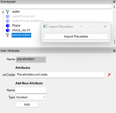
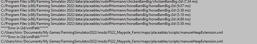 1 point
 -
I have updated these scripts to use the new pop up panel format currently in GE 9.0.4. The original scripts will still be available should you prefer to use them as sometimes the operation of these new versions may seem a little slower. Refer to the relevant tutorials on ways of using these new scripts Terrain Height,Paint Terrain and Spline Placement scripts (Tutorials) Create Field Dimensions and Farmlands Tutorial Spline Panels.zip available at the end of this topic Installation, copy paste the Spline Panel folder into the C:/Users/Your Computer Name/AppData/Local/GIANTS Editor 64bit 9.0.4/scripts Folder. Spline Paint Panel This is the updated version of the Spline Paint script and no longer needs a separate Set Up script to create User Attributes or a separate Terrain Layers script to print the terrain Layer no as a reference. The script itself works roughly the same way as the previous version so parts of the tutorial are still relevant regarding operation. Texture’s are now automatically read from the map.i3d and selected by using the relevant drop down arrows, any additional textures created and added to the map.i3d will also be automatically added to the drop down selections. The script only needs to be activated once further execution is done via the Paint Button. To activate the Paint Terrain by Spline pop up, in GE -- Scripts—Spline Paint Panel the following panel will it appear. Measurements can be inputted manually (recommended) or by using the sliders <> next to the relevant boxes. Example image showing texture drop down with DIRT Selected Once you have made your selections ensure the spline is selected (if no spline selected a warning will appear in the console log) and select the Paint button at the bottom. Other splines can be used simply by selecting them adding any new settings and selecting Paint. Random Paint is carried out the same as before, this time by selecting Selected in the drop down then add your settings and select the Paint Button. Individual sides of random paint(left or right) can also be selected by selecting -1 (at the bottom of the drop down list) in the non painting edge texture drop down. Spline Height Panel This updated script no longer requires a separate Set Up script or use User Attributes to work. Activate the Set Terrain Height by Spline pop up in GE by selecting Script—Spline Height Panel this only needs to be done once in each session as the Panel can be used with other splines without further activation, execution of any new settings being carried out by selecting the Set Height button The settings can be set either manually or by using the slider <>. A spline can be selected before or after filling in the various settings, if a spline is not selected a warning will appear in the console log prompting you to select a spline When happy with values and with a spline selected, select the Set Height button at the bottom of the panel to activate the script. There are some restrictions on minimum/maximum values, Set Centre Width – 0 to 255m Set Spline Height -- -50 to 255m (-50 to allow for spline transformations on higher terrain) Set Edge Width -- 0 to 50m Set Edge Height Left/right -- -20 to 20 Set Edge Smooth Left/Right – 1 to 20 Set Distance Between Points – 0.5 to 100 The existing tutorial on Spline Height can still be used for reference. An updated version of the Spline CSV Creator Panels script is available here https://farmerboysmodding.com/index.php?/topic/2471-spline-csv-creator-panel-updated/ This new version creates a spline.obj file from the newly created spline for direct import into Blender without the need to convert from a .csv file This spline.obj will still need converting to a curve in Blender to create roads etc. Spline CSV Creator Panel This updated script again no longer needs a Set Up script to initialise User Attributes to work. It now does not need a map name inputted as the script automatically puts the CSVdata folder created by the script and containing the new spline.i3d and splineCsvData.txt files in the same folder as the map.i3d Activate the CSV Creator pop up by selecting Scripts – Spline CSV Creator Panel in Select a spline, enter the distance required between CSV points and select the Create CSV button. Other splines can also be used by repeating the above ensuring that any new splines have a different name. Used in conjunction with the Blender Plugin for CSV Data Field Creation(Dimension) Scripts These are in a separate folder called Field Creation Scripts and consist of three separate scripts that are needed to perform a complete field creation. Create_FieldDimensions Panel The pop up Create Field Dimensions is activated in GE by selecting Scripts—Field Creation Scripts - Create Field Dimensions Panel No further activation is required as further script execution is now done by the Create Field Dimension button The FieldDimension_SetUp script is no longer required as the Create Field Dimensions Panel script when activated now automatically creates a new transform Group in the scenegraph 'Field_Creation_Transform' with all the required transform groups. Create_Field_Dimension pop up The Main Fields transform to create the fieldDimensions will be the fieldsNew –fields transform group and Markers transform newFieldMarkers – Markers. Field dimensions created for the Paint Farmland Field xml Panel will use the farmlandDimensions –fields transform group and the same Markers TG (once the markers have been reset to suit) Once the markers are created select the relevant fields transform enter the field no and select the Create Field Dimension button to execute the script. Any duplicate field numbers will activate a warning text in the console log. Paint Farmland Field xml Panel This panel is activated in GE by selecting Scripts—Field Creation Scripts – Paint Farmland Field xml Panels Panel. As is the case with the other scripts no further activation is required as all execution is done by the Create Farmlands button Set Path to XML – gives two choices farmlands.xml, if your farmlands.xml is in the same folder as your map.i3d or xml/farmlands.xml if you farmland.xml is in a separate xml folder in your map.i3d folder. These two paths are the most commonly used by map makers if you have the farmlands.xml elsewhere then I suggest moving it temporarily to the map.i3d folder. Set Total Fields – this is adjustable either by manual entry (recommended) or by the slider <> between 1 and 255 the 130 is an arbitrary figure farmlands.xml entries will still only show your actual field numbers. Set Land Price – is the multiplier applied to any land prices adjustable either by manual entry (recommended) or by the slider <> between 0 and 10 Set NPC Area – Allows choosing of an NPC area "ALPINE","US","FR" from the drop down selection can be different for each field if required. Number of Different NPC’s -- This is the number of different NPC’s available in the base scripts a number between 1 and 15 is randomly chosen by the script or can be selected manually for each field ownership created. Number can be increased if map maker has added extra NPC’s. Show on Farmlands Screen – If Yes then the field is shown on the games Farmlands screen, No the field will not be shown, used in cases where the farmland is bought with a placeable i.e. BGA Default Farm Property – Yes assigns that field to the ownership of the default (player) farm, No field is then buyable in the normal manner. Once all the relevant details have been entered select the farmlandDimensions –fields –field01 for example and select the Create Farmlands button. The infoLayer_farmlands.grle will have been painted (can be checked in GE by selecting the Terrain Info Layer Paint Mode together with the Info Layer –farmland and the Lands Farmlands number) and an entry for that field created in the farmlands.xml the field number being obtained from the field name i.e field01 will be Field01 in the farmlands.xml Warnings will appear in the log if a field number already exists in the farmlands.xml Subsequent fields can be created by selecting the next field number in the farmlandDimensions –fields transform and selecting Create Farmlands I have included the Paint Field Ground Foliage script (although not yet updated, WIP) together with its reference image, in this folder to keep all the scripts for Field Creation together. A little tip for speedily resetting the markers to create the new field dimensions for the Paint Farmland Farmlands xml script is to scale the X and Z axis by a factor of 0.1/2 depending on size required, (marker size has no effect on actual position) but bear in mind the scaling will be done with reference to the Markers TG (fieldmapIndicator position) so could appear distorted depending on position Spline Place and Spline Foliage scripts will also be updated to use the new pop up panel system in due course. Further information and guidance can be currently found in the Create Field Dimensions and Farmlands Tutorial, though this will also be updated in due course to reflect the changes. Spline Panels.zip1 point
-
Paint Foliage by Spline Panel This script is slightly different to the previous version in that it only paints in one area whereas the previous script painted in two independent area’s, this has been done to increase the stability of the script and also improve the Random Foliage Paint option. The script now automatically reads the map.i3d to list in the UI drop downs, all the Foliage Type’s associated with your map so there is no longer any need to add any extra foliage/crop to the script. However the Foliage State for each Foliage Type still requires a number value (position in the Layer State dropdown in GE) To assist with this the script now reads all the Foliage States of each Foliage Type directly from the maps foliage folder xml’s and prints result to the console log and to a foliage_States.txt file in the same folder as the map.i3d for easy reference, the image below shows the extracts from console log print out and the foliage_States.txt file . The foliage states listed here are from a test map based on the US map so yours may differ depending on your map set up. The script allows for a max no of Foliage/Crop Types = 100 and max no of individual Foliage States = 20 To undo any of the Foliage Layers, Set Foliage State to '0' and ensure Random Foliage Paint is deselected then Select Paint Foliage The script ignores any entry in the Set Foliage State if Random Foliage Paint is selected Unzip the Paint Foliage by Spline.zip (found at the end of the tutorial) and place the script in:- C:/Users/Your Computer Name/AppData/Local/GIANTS Editor 64bit 9.0.6/scripts The script requires the Farming Simulator 2022 installation path , it is set at a default of “C:/Program Files (x86)/Farming Simulator 2022” If your installation path is different then, Open Giants Editor, Select -- Window --Script Editor and navigate to where you have placed the new script and select it. Once opened, in the editor go to line 30 local gInst = “C:/Program Files (x86)/Farming Simulator 2022” and replace the entry (after the 😃 with your installation path including quotes Once done save the script, the Script Editor window can now be closed as the script is now ready to be used. Paint Foliage Open the script in GE Select -Scripts –Paint Foliage by Spline Panel a popup panel will appear on the screen Set Overall Width Width of area to be painted Set Offset Paint Distance Distance either side and away from the spline to be painted e.g A setting of 10 will paint foliage 10m to the left of the spline at the width set Set Foliage Type Select Foliage Type from the dropdown Set Foliage State This number when entered refers to the Foliage State 0,1,2 etc of the selected Foliage, refer to the Foliage State print out in the console log or to the foliage_States.txt file in the map.i3d folder for the associated numbers and foliage state types. Set Second Foliage State This number refers to the second Foliage State value used by the Variable Foliage State option and is only relevant if Variable Foliage State and Random Foliage Paint options are selected Variable Foliage State When selected along with Random Foliage Paint option allows only parts of the Foliage Types States to be randomly painted, see further description below Random Foliage Paint When selected allows random painting of all the foliage States for the selected Foliage along and around the spline To delete foliage after using, Random Foliage Paint must be deselected and ‘0’ entered in the Set Foliage State box Random Foliage Distance When selected paints the selected foliage at a random distance along the Spline, width of paint is controlled by the Overall Width setting Set Distance Between Foliage Paints the foliage at the distance set along the spline, width of paint is controlled by the Overall Width setting. Variable Foliage State Option This option allows the choice of which section of the Foliage Type States are to be randomly painted along/around the spline. It is only used in conjunction with the Random Foliage Paint. For example with Variable Foliage State and Random Foliage Paint selected and the other inputs set as follows Set Overall Width - 10 Set Foliage Type – groundFoliage, Set Foliage State – 7, Set Second Foliage State – 14 It will only randomly paint foliage states 7 (cover foliage) to 14 (stinging nettles) in a path 10m long along/around the spline. To delete foliage, Random Foliage Paint must be deselected and ‘0’ entered in Set Foliage State panel. If any of the random options have been used then there will be some bits of foliage left (due to the random paint). This can easily be deleted by selecting the relevant foliage layer in the Foliage Layer Painting panel in GE and using the subtract brush. When painting foliage using the same densityMap.gdm any existing foliage it will be erased by the new foliage. Normally the ground foliage ,stone and weed use separate density maps all other foliage use the densityMap_fruits.gdm. The following images show the script in basic operations Note: The over painting at either end of the spline is due to the Random Foliage Paint which will paint the selected foliage, foliage states at random along and around the spline This can easily be deleted by selecting the relevant foliage layer in the Foliage Layer Painting panel in GE and using the subtract brush. Bear in mind the wider and longer the painting the longer the script will take to work, the Paint Foliage button will turn blue when activated, when it turns white the script has finished. As always play around with the script on a blank map to see what effects you can obtain before using on a WIP map. The next image shows a short road/lane section created using the Spline Paint Panel and the Paint Foliage by Spline Panel scripts. Paint Foliage by Spline Panel.zip1 point
-
View File FS17_Joransfarm Why the name Joran’s Farm? Joran was a 14 year old kid who was a huge fan of my first map. He dreamed of having his own map and to learn modding himself. He was a very friendly and a smart kid who was fighting cancer. I started to work with him and we had daily contact. I started to create a map for him with his name. Some of the items on this map he created or reskinned himself. Most things and play-style on this map were his idea. Sadly he lost his fight against cancer 28 May 2018. I made the landing point on the map into a memorial for Joran. Please take a look and hold a minute of silence for him. This map requires mods that are not included with the map. You can find the mods that are required for the map to function properly here. Required Mods Submitter Maverick74 Submitted 01/10/2019 Category FS17 mods CREDITS Modders who helped me or I get stuff from: -Joran (ideas and mods) -bdbssb (mods and help) -shywizard (mods and help) -farmer Andy (mods) -gtx Andy (mods) -kevink98 (scripts) -igor29381 (script for the trailer and some buildings) -blacksheep – rc-devil (scripts) -jolydodger (utility van) -billy_boyd42 (testing) -ronny sell (testing) -jacershepherd (this document) • And a big thank you to all modders of buildings and stuff • Without all these people I couldn’t build a map. • RESPECT!!!1 point
-
No, new snow meshes can only be created in Blender/Maya. However you may be able to use exsiting snow roof mesh i3ds if they fit the roof/building you have made in Blender/Maya1 point
-
Just as aside I personally don't use Spline Street Constructer as I prefer the Blender method as it is much more flexible and allows creation of custom junctions. I believe Bauer Brown has recently done a 30min video using this method Further tutorial available here https://farmerboysmodding.com/index.php?/topic/2413-export-a-spline-from-giants-editor-into-blender-to-create-roadsrailways-updated/1 point
-
SNOW MASK This is just a follow on from a previous post regarding the Scripts -Generate Mask script that automatically creates an indoor snow mask (infoLayer_indoorMask.grle) by mapping the collision footprint of objects in the map roads, buildings etc (placeables should have their own mask already created in the i3d). The Generate Mask script originally worked by using the water plane height (inputted manually into the script)as a base for calculations as this was normally the lowest point on the map, however this is sometimes no longer the case. The problem highlighted by Dickieboy in his post (https://farmerboysmodding.com/index.php?/topic/2446-indoor-mask/) was that the script had a preset height of 47.5m which when executed without any change caused unwanted blocks to appear in the finished grle image. I have now edited the original script and renamed it (to avoid confusion with the original) so that it now allows the mask height to be set. The updated script is available at the end of this post, to install download the Create Snow Mask.zip and unzip, copy/paste the Create Snow Mask folder into C:\Users\Your Computer Name\AppData\Local\GIANTS Editor 64bit 9.0.4\scripts To use In Giants Editor Select Scripts – Snow Mask – Create Snow Mask the following pop up panel will appear Height Setting The height needs to set at the terrains lowest point, if you are unsure of the lowest point then a simple method to find this out is to Create -_Primitives – Plane and adjust the X and Z scales so the plane fits the size of your map (2048 for a normal size map) and just lower the plane until it is no longer visible in the map. Once happy with your height settings enter the figure into the Set Mask Height panel and select Generate Snow Mask the button will turn blue to show the script is working. WARNING – The script can take a couple of minutes to work (depending on how many collisions are in the map) during this time DO NOT try and do anything else in Giants Editor as it will freeze/crash. When the script has finished the Generate Snow Mask button will turn white and the following information will be printed in the console log, in this case, Saving mask map to C:/Users/Your Computer Name/Documents/My FS 22 Mods/Mod_Map_Alpine/maps/mapAlpine/map.i3d.indoorMask.grle Snow Height Set to: 5.0 You can of course leave the height setting at 0 (zero) but, although this will work it will take a bit longer for the script to finish. The new map.i3d.indoorMask.grle will probably need to be edited as items like rocks/boulders meshes will be clear of snow. This can be done in an image editor or in Giants Editor, I prefer doing any editing in Giants Editor as I then have a reference for adjusting the edit (such as lanes and by roads which if created with a mesh will not have any snow cover) and will not have to reconvert from png to grle. To edit in GE first you will need to rename/delete the original infoLayer_indoorMask.grle in the data folder and rename the map.i3d.indoorMask.grle to infoLayer_indoorMask.grle and copy/paste into the data folder . Open your map in GE and Select the Terrain info layer paint mode then in the Terrain Editing panel –Info Layer Painting –info layer dropdown select indoorMask the State Panel will change to Outdoor and the map area will turn white (snow) with pink areas (no snow). Select Info Channel 0 map will then change to white (no snow) and partially transparent black (snow) Right click paints a no snow area Left click deletes a no snow area When finished editing save the map the new snow mask will be saved in the infoLayer_indoorMask.grle Below are some examples of the new snow masks compared with existing in game versions ALPINE Map - height set at 5 -- original in game image on the right USA Map - height set at 65 -- original ingame image on the right Another thing to note is if you have both a infoLayer_indoorMask.grle and infoLayer_indoorMask.png in your data folder at the same time Giants Editor may crash on loading. Create Snow Mask.zip1 point
-
The past Year I have been teaching myself Houdini, which I thought would be the ultimate "do it all" tool for maps. 🙂 With the toolkit I've made I can create roads which will adapt to and adjust the heightmap (including AI and traffic splines) create railway tracks which will adapt to and adjust the heightmap, and create the required spline for the train system create road barriers create cascading rivers with flowmaps create field dimensions which at the same time will smooth the rough terrain beneath, and export helper objects to create all the field dimensions in one click in GE texture the map using different selectors such as slope and height, road and railroad mask scatter rocks and cliffs based on different rules scatter trees based on different rules I Have more ideas for tools in the future! Below is a sample of most of the tools combined and how one tool can dictate where the next is allowed to work. For instance a road will create a mask, which tells the tree scatter tool that it cannot spawn trees there.1 point
-
From the tutorial - - https://farmerboysmodding.com/index.php?/topic/2414-terrain-height-paint-terrain-and-spline-placement-scripts-tutorials/ With this script objects can be placed at various fixed, preset distances, random distances and locations away from or along the spline depending on settings in the script. The objects will be placed at terrain height along the spline (using their individual point of origin location) from the 'S' cv to the ‘E’ cv and aligned to the to the spline along their "Z" axis (unless random location selected). e.g. if you have a hedge that is 4m long and 1m wide ensure the longest section (4m)is aligned to the 'Z' axis otherwise rotate it in GE until is aligned along the 'Z' axis and freeze transform rotation also ensure that the point of origin (where the gizmo shows when object is selected) is at the correct point For best results, open any objects you intend to place in GE and adjust axis and origin accordingly, when done , freeze transform all scale/rotation settings (DO NOT freeze transform translations unless point of origin is relocated) on all the relevant objects. This also applies to any transform groups containing objects that required to be placed using the transform group itself, select the transform group and Edit—Freeze Transformation—Transformation, Rotation and scale1 point
-
There is another problem with the 9.0.4 version of Giants Editor that occurs when exporting terrain as an obj file. Previously when exporting you could limit what section of terrain you wanted to export by just using the viewport window a sort of what you see is what you get. Unfortunately wth this current version when you export the terrain you export the WHOLE terrain regardless of the viewport settings./position which can lead to problems with low spec computers.1 point
-
Further info regarding splines. It would appear that selecting the 'E' end of the spline (which I thought denoted the End of the spline) and selecting INSERT on the keyboard the new cv is inserted BUT the gizmo does not move to the new cv setting but remains on the previous one requiring the down arrow to be selected before Ctrl B placing of the new cv If the down arrow is not selected before inserting anothe cv (on the 'E' endof the spline) the subsequent cv's will be placed back along the spline towards the 'S' cv However selecting the 'S' cv and selecting INSERT on the keyboard the new cv is inserted and the gizmo moves to the new cv location so not requiring the down arrow to be selected before Ctrl B placing I find it hard to see how this set up is an 'improvement'1 point
-
To avoid problems with spline rotation do the following Create -- spline then zoom in and delete the 'S' cv this will move the rotation point ans the 'S' cv to the spline transform settings then create your spline layout by just using the 'E' cv Again from the Tutorial1 point
-
Did you rotate the spline from EW to NS ? If so you MUST freeze rotate transformtions ( Edit --Freeze Transformations--- and just select Rotate then Apply ) before running script otherwise you will get some strange results.1 point
-
The minimum edge width of 1m is set to to allow further blending ( if necessary) and to counteract the way GE paints a 2m terrain section, however if you wish to set a lower value then adjust the following line in the Terrain Paint R script Line 108 --- if edgeWidth >= 1 and i > offset then to Line 108 --- if edgeWidth >= 0 and i > offset then However because of the way GE paints the terrain the edges will not be smooth or as easily adjustable compared with the 1m distance. For example set the Terrain Editing Brush to 0.25 (equivalent to a 0.5m distance) and try painting a curve and you will see that it misses sections.1 point
-
Does this mean you no longer have a problem ?1 point
-
This is something iv'e been working on for a while. Started back in Farming Simulator 17 but never got the time to complete it. After the release of Seasons mod i always wanted a way to be able to actually do something with the snow. Creating a sell point & just being able to sell the snow seemed the easy option imo. So here is my Snow Dragon snow melter for Farming Simulator 19
 1 point
 -
Glad that change solved your problem, as I said I will do some further test with both of the scripts that use that sequence (Terrain Height,Terrain Paint) before updating the Updated Spline Scripts.zip package with the new settings.1 point
-
View File FS17 Joransfarm transportPack This pack is edited and reskinned for the use on FS17_Joransfarm. It's used to transport factory products on this map. There's also an autoloader flatbed with trailer that can be used for bales,wool that aren't factory related on the map. Submitter Maverick74 Submitted 01/10/2019 Category JoransFarm equipment CREDITS Transport-Pack Credits: Original - ATC Pack Concept - Alfredix Models - Alfredix Testing - Alfredix, Meerstonk, Mach1-Andy, Farmerfivetom, Legolas2905 Schemas - V8Bolle Soundmixers - 8x8 Semi HD truck sounds, 10 x 10TGS Chassis, Soundscout, Ralfrhoen, Truck sound video Script - ifkonator (addStoreCategory, AddConfig) - Xentro (dynamic Hoses) - Hot Team ( UAL) - Blacky BPG (Hotspotfix, licenseplatescript) - GTX (LightExtension RealCab) - Martin Fabik (no smoke no fun) - Modelleicher (newExhaustEffects) Model sources GTX (Drawbar for TSDH trailers, Decals for Cab interiour, Signal Lights, AR flatbed) Gnescher (original AR Pack) PhillipDeutz (Traileraxle) Giants (MAN TGS 18,480) Kastor (Pallets, Fillplanes for fridges) ImplementHelp - Meerstonk Joran´s Farm Rework NCRaiders, Maverick74, Igor29381, LS-for-Ever1 point
-
Scripts have been Updated, now use User Attributes for entry of data.1 point
-
Thank you for telling me I apologise profusely, with all the problems getting stuff uploaded I forgot to add the zip file, now corrected and zip added1 point
-
Blender 2.93 and later Mapping-- Coordinates --Generated---- now part of the Displacement setting Influence --Deselct Color Select –Intensity -- now part of the BSDF shader color/specul;ar etc However I am using another method in Blender 3.1 that seems to give reasonable result Blender 3.1 (make sure the Render Engine is set to Cycles), (remember to first download and install the Blender Exporter V9.0.1 from https://gdn.giants-software.com/downloads.php) 8kBorderGE image and 8kBorderDem4096 were both created using the snipping tool in Google Earth both saved as RGB pngs In the first image I have created a mesh (Import Image as Plane) with the 8k RGB border texture and added the 8kBorderDem4096 texture I will use for the displacement Main settings are Mapping -- Extension --Extend --this gives a clean edge to the border by extending the edge pixels Clamp -- Deselected -- this allows the full colour range to be used in the displacement All other settings can be left as default though it may be necessary, depending on the dem to set the Color Space to Linear to get better results. Next the 8k border mesh has been subdivided 20 times and Displacment modifier added, Texture coordinates must be set to UV although no UV map is required. and lastly the final settings for alignment to the terrain In the Item pop out you will notice that the Z Location value is different to the Z value in the Dimensions -134.69 and 138 respectively this is to show the GE border area more clearly otherwise it would be mixed in with the border image. Regarding the Dimension Z value (138 in this case) this is normally the highest point of your terrain over the whole border area but can differ due to monitor colour settings and displacement strengths so it is always best to adjust to imported GE terrain. Highest point can easily be found by running cursor over the area in Google Earth and checking the elev figure in the bottom right Don't forget to set shading to smooth (Object-Shade Smooth) and Ctrl-A (Set Scale and location if mesh reset to 0) before exporting i3d When time permits I will be overhauling/updating all the tutorials to reflect the latest updates to links and software.1 point
-
Awesome job @Dogfacety for this. This is a very powerful tool guys and gals. I’ve been using it to make some cool looking effects. With @Dogfaceinstructions this is how I made the effects for the stone picker I uploaded.1 point
-
Here is another example of what can be achieved using the correct texture shaders Unfortunately the way the textures are dealt with currently in FS19 (and it appears that FS22 will use the same format ) you get a stretching of the texture at high bump levels as shown in the following image image factsheet from FS22 The stretching could be passed of as slicing like the following image but it still doesn't look qiute right and I hope they correct it in the final version of FS22. The following has been created from the acre_plantedRow texture from the ground_diffuse array in FS19 and shows how with the right combination of images and shader realistic texture can be created. In the attached zip file are all the textures created in Materialize so you can experiment for yourselves from a known base just unzip and open them in the relevant slots in Materialize, also in the zip is an i3d Plane with a lighter acre_plantedRow texture (for better definition) and an acre_Planted_Normal_2 created by using the following format (roughly the same as in FS19) so you can see/experiment with different settings in Giants Editor. Red Channel -- normal map red channel from Materialize, Green channel -- edge texture from Materialize, Blue channel filled with white Alpha channel -- Height texture from Materialize It seems the maximum Bump Depth appears to be 2 before stretching occurs in all cases where the height map is used in the Alpha channel of the normal map. acre_PlantedRow_textures.zip1 point
-
Usually with the new versions o f microdem you either slect the GooglEarth globe in the toolbar or right click on the map and select Export where you are given a choice between quick and deliberate export to Google Earth, however there seems to be a bug in the programme now that doesn't allow adjustment of opacity in Google Earth so you are left with a partially visible srtm and another bug, as you have found, id that it no longer saves as aGeoTiff but as a .tif image. The only soloution I can suggest at the moment is to find an earlier version of the Microdem programme which appear to work as normal or use QGIS (free full blown geospatial programme)1 point
-
but if i changed in viehcle xml what would happen ? well if something changed there that have connection to moddesc/l10n it would break if not also changed in there1 point
-
Huge thanks to fscommando for getting the site setup to add this video.1 point
-
Correct @Poorboy good find. For those of you who aren’t aware if you make a new map from a previous one it will usually have an existing tip collision mask. You need to paint a new one because the original map will have all the road areas and buildings painted so that material can’t be dumped on those areas. What will happen is when you mow grass or even for example straw windrowed will not appear in those areas but then mound up as soon as you hit a spot that doesn’t have the painted area. You have to remove all tip collision area and re paint then run the script.1 point
-
If you’re too lazy to do the torque to HP math 😂
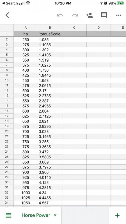 1 point
 -
Just a quick note regarding Microdem, on the newer versions you will need to right click in the map area to bring up the full Display Parameters option. Also if when drag dropping .tif into Google Earth it is basically a whiteout, open in Microdem and either Save map as image --Geotiff (greyscale or Quick (or Deleiberate) map export to Google Earth only change the z range if necessary. If you have further problems like high areas of your dem not translating properly and flattening out ( normally high brightness) in Giants Editor then open SRTM in MIcrodem and adjust the upper zRange to lower zRange + 255 this will spread the greyscale over a larger range, this has the effect of darkening the SRTM as the upper hight values now use a lower part of the greyscale band, the height values of the final dem should not be affected.1 point
-
Don’t worry about glitch. It was a stupid mod that was active automatically when I brought the tractor. It did same thing on the hulk tipper.1 point
-
New to this site. You can thank nick the hick. For putting me on to you. Well done on the mod thanks. One minor glitch. You can’t tab into this tractor. I’m not sure it’s a mod conflict, a glitch or the way you have intended it to be Other then that, very well done! And thank you for adding dual narrows. Is there a file for the hp torque chart? thanks again to the team here . I do appreciate it1 point
-
Sorry Issa I adjusted the fuel trigger on the fuel fermenter, it should work now.1 point
-
Open map in GE goto Windows(C) -Programme Files(x86)--Farming Simulator 2019 --data- maps -trees and import the releveant i3d into your map (i.e. birch.i3d) in GE --Edit --Replace -- a Replace box will open Select the tree you want to replace and and select "Load" in the "Target Section" i.e birch_stage_3 Select from the imported birch.i3d the tree you want to use to replace the original i.e birch_stage_4 (or any other size for that matter) Select "Load" in the "Replace with" section you should now have , "Target" --the tree you are replacing and "Replace With" the tree you are using as your replacement. Select Replace All Every tree of the type you selected on the map as the Target has now been replaced with the tree you selected in Replace With retaining original scale and translations. Save and rezip map.1 point
-
Thanks for pointing that out. Here is the thing with that both those bars and the wires can act up at times. it isn't something i can fix as everything is setup properly on the header it just goes out of wack when folding and unfolding at times. I have looked at it a few times just to make sure i didn't mess something up and everything is done properly. I have even had it not move those part one time then a few days later when i am using it again the parts move properly and go back into the proper position.1 point