
Leaderboard


Popular Content
Showing content with the highest reputation since 01/15/2019 in all areas
-
Version 31.10.20.05
2,073 downloads
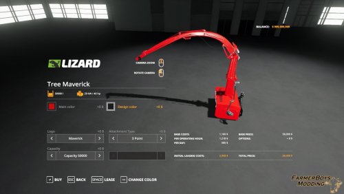
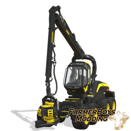
Originally this mod was started as just a minor upgrade to the bruks to fix the major texture issues. I worked with Bigdaddy in the beginning to help me fine tune it. After working on it i decided to just replace the entire model itself. So i made a new box for it and cut the pipe and crusher wheels off existing giants equipment. I continued to tune it after that. I asked BDBSSB for help on some texturing and he kindly helped me get the new box textured properly. I then had him help me add a motor and wiring, and also had him add in new frame attacher options based on attachment type you want to use. After that he helped me do some final tuning in the xml at which point there was nothing really left of the original xml file as we had redone 95% of it. We decided to dedicate the mod to a fellow mod maker named Maverick74 that has made maps in fs17. We have not been able to get ahold of him in the last 6 months so it was decided then to dedicate this new mod to him. Though we hope nothing has happened to him. The stump grinder is on the bottom of tree maverick. if you lower it enough you can just drive forwards to grind the stump without having to lift the machine. Mod Store Options: Selectable attachment type Selectable Maverick74 logo (visible or not) Selectable main color Selectable design color: decals 4 capacity options: 50k default, 500k, 1 million, and 3 million. Capacity upgrades have a cost to purchase.10 points -
Version 25.06.23.01
663 downloads
25.06.23.01 Update Added the mks32 semi trailer (with hitch), added hitch to the mks8, added selectable material to all tanks (select material then color separate). Also changed some gui descriptions in the production menus to match the fermanure setup. 06.02.23.01 So sorry for just noticing this but original speed on this was horrible. I upped from 10k on fermenting per hour to 125K which is comparable to the FS19 version. I will look at the other buildings for adjustments as well. 14.01.23.01 Large update Videos below Since adding the fuel tank to the fermenter placeable it has had 3 loading triggers but 2 have been on top of one another and the 3rd is by the fuel tank for equipment refuel. However some time back viper was asking me about issues using autodrive and loading unloading. I think after spending some ingame time I may have figured it out. I have now moved one of the loading triggers off to the side, I think the 2 triggers being on top of one another was causing the issue. I added a service trailer it is simply the thunder creek from in game however it will load everything including liquid. Both the small additive tank and large tank that were previously included will now haul all liquids, fill and overload to other equipment as well as refuel equipment. The thunder creek trailer works the same as the two tanks however because it can be filled with anything it can fill seeders with seed, solid fertilizer, or liquid fertilizer. ALSO I did some xml work that will cause any trailer in game to now haul silage additive, I did this so you would not need a stand alone tank. If anyone has any issues with this new update please let me know asap. I have much faster response time on discord My discord invite. Update Version 04.11.22.01 Sped up bale deletion Update Version 03.11.22.01 Added bale trigger to input. Update Version 08.01.22.01 added a trigger next to the small fuel tank to refuel equipment Update Version 31.12.21.01 added mass update false to towable tank. Enlarged liquid trigger on output of silo. Update Version 30.12.21.01 Added silage additive to production line takes liquid fertilizer and digestate to make silage additive. Also edited the small sprayer tank to haul the silage additive (could not add to other tank because additive is not in category). The tank is found in the misc category. The small tank will overload to balers and loading wagons. I expanded the additive fill area of the magnon windrower wagon to fill directly from the production building easier. Fyi sialge additive adds about 5% yield to grass only. This fermenter uses the in game production lines. It will produce Silage from straw, chaff, grass, or woodchips. The silo will store the silage or you can start secondary productions with the made silage or silage dumped in to the silo. Silage will produce fertilizer, liquid fertilizer, or diesel. When producing these products it will also produce a small amount of digestate. The silo will also store all products involved with production. Included with the pack is a trailer found in the misc section. It is the MKS8 small trailer modified to accept all liquids in game. It will dump in to the silo, load from the silo, or fuel equipment. I havent tested all equipment however i was able to fill the aeon 5200 from the silo and tank. Per 30.12.21.01 update a small tank was added to haul silage additive as well. TO USE PRODUCTION To get to productions hit P and go down to the dashed lines thenselect construction, then production. If you have no other production mods it will be all the way to the right and named fermenter. Once you put material in the silo you will need to activate the production. To do this hit escape and click on the production icon, i believe its right under contracts. Then you simply select each line and hit activate on the bottom. 1 (17).mp4 1 (11).mp4 1 (12).mp4 1 (13).mp4 1 (14).mp48 points -
Version 8.12.19.2
1,374 downloads
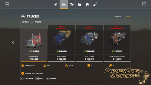
To refuel the tanker truck only put the cab into the fuel trigger. If you want to fill the tank only have the tank in the trigger. if both the cab and tank are in the trigger it will only try an fill the trucks fuel tank and not the tanker portion. This is a truck pack with the following trucks. Tipper Truck Capacity: 48000 Capacity options: 500k, 1 mil, or 3mil Tanker Truck Capacity: 30000 Capacity options: 500k, 1 mil, or 3mil Slurry Spreader Truck Capacity: 30000 Capacity options: 500k, 1 mil, or 3mil Mnure Spreader Truck Capacity: 32000 Capacity options: 50k, 100k, or 200k Flatbed Truck Wood Truck with optional autoload They also have 3 tip speed options default, fast discharge of 100k, and super discharge of 250k Tanker Truck can haul any liquid that is in the folowing catagories LIQUID, SLURRYTANK, or SPRAYER The trucks have the following: 4 engine choices color selection added work lights to the rear The slurry spreader truck has a 32m working width with a reduced usage amount on digestate and liquid manure. The manure spreaderhas a 32m work width and has a reduced usage when spreading Choice of 4 wheel options The choice was made by me to not have a rear hitch and i will not add them to the trucks.8 points -
Version 16.12.19.1
1,624 downloads
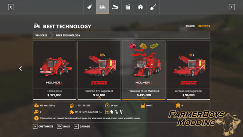
This is a modified T4-40 harvester and header setup. I made the headers 16.7m wide and foldable. I added potato and sugarcane to the beet harvester and made seperate headers for all 3 crops. I added decals to the back of all the headers to help tell them apart. I raised the capacity on the T4-40 to 60,000 and sped the working speed of the headers up to 12mph/20kph. I made a separate T4-40 harvester and header setup just for cotton. I lowered the price of the T4-40 cotton harvester to be were when the header is bought with it it is slightly cheaper than the ingame cotton harvester. On the cotton harvester there is no unloading effect from the belt as giants never ment cotton to be a loose product like i made it. I modified a semi trailer and a trailer designed to be pulled by a tractor to hual all the crops that the pack can harvest.7 points -
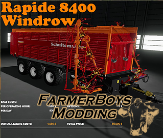
Version 12.04.20.01
3,085 downloads
Latest version 12.04.20.01 Added color decals, added chrome option for wheels. Rapide 8400W with added capacity and windrowers Cat: Loading Wagon Capacity: Standard: 100,000 Extension: 150,000 Working Speed: 30kph/18mph Price: $80,000 Major update, huge thanks to NcRaiders as always for some awesome work. He was able to get the windrowers worked in to the mod as an addon option in the store. By default the wagon will have the windrowers with a 21m width. I set the price to 78k and the addon is 2k. With all the updates, it wouldn't be a bad idea to sell and rebuy the wagon. I can't guarantee its needed, can't guarantee you won't have any issues if you don't. List of changes: Windrower option in store Color selectable rims Fixed foliage bending Added rotating parts into the color scheme, now they change color as well Upped the intake liter per hour(machine was shutting down if you went in to a large pile) Arms now have to be unfolded (another fix by NcRaiders) to start the machine (more realistic). Obviously you can't pick up material with arms folded now. Added sound to arm motors while unfold/fold.6 points -
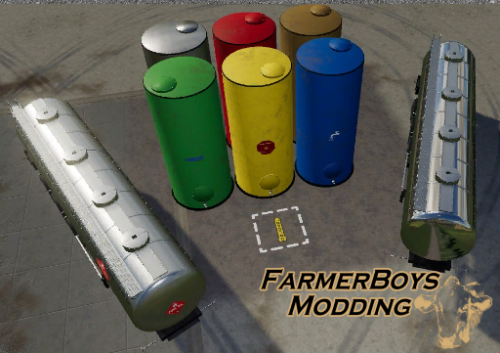
Version 14.11.19.00
1,362 downloads
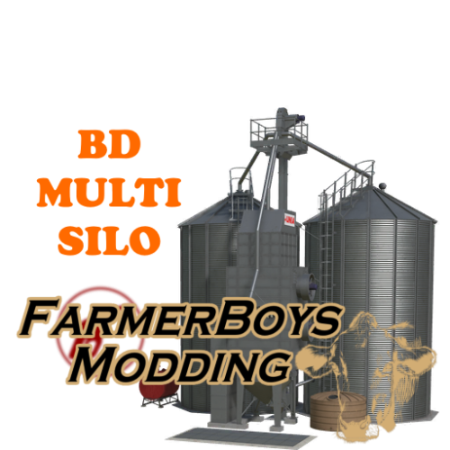
Liquid Storage Pack <version>07.10.19.00</version> Just added the ability for the tank trailers to haul all materials so now you can fill your seeders with seed and fertilizer from them as well! <version>03.10.19.00</version> Major update. Please be sure to empty and sell your fuel tanks before installing this update. I have removed the fuel trailers because they aren't needed anymore. Equipment will refuel from all tanks now. Most important the tanks will all overload and fill all in game tanks and sprayers, sorry for taking so long, I found a collision error. I also added a high capacity to all tanks as well. This is a liquid tank placeable pack that includes trailer tankers needed to transport all liquids as well. The placeable tank will be in the silo category of the store, the trailer tanks will be in the misc category of the vehicles. I also added a pin lock to the Liquid/Fuel 25 tanks. This means when the lock is activated the small front dolly will not rotate. This allows for easier backing (Pin Lock Option uses default folding buttons). Liquid Storage Price: 110,000 Capacity: 10,000,000 (per product) Fill type: Milk, Water, Liquid Fertilizer, Herbicide, Liquid Manure, Digestate, Diesel Placeable/Silos Liquid Tank 75 Price: 68,000 Capacity: 60,000 High Capacity: 200,000 ($3,500) Tires: Default, Wide Rims: Chrome, Stainless, Full color grid Body Color: Chrome, Stainless, Full color grid Fill type: All default liquids Uses categories Liquid, Sprayer, Slurrytank. As long as a map maker uses categories all liquids should be compatible. Tank will overload to other tanks, and will fuel equipment. Liquid Tank 75D Price: 75,000 (has a dolly built in, option to pin lock) Capacity: 60,000 High Capacity: 200,000 ($3,500) Tires: Default, Wide Rims: Chrome, Stainless, Full color grid Body Color: Chrome, Stainless, Full color grid Fill type: All default liquids Uses categories Liquid, Sprayer, Slurrytank. As long as a map maker uses categories all liquids should be compatible. Tank will overload to other tanks, and will fuel equipment. Liquid Tank 25 (Pin Lock Option uses default folding buttons) Price: 25,000 Capacity: 25,000 High Capacity: 75,000 ($3,500) Tires: Default, Wide Rims: Chrome, Stainless, Full color grid Body Color: Chrome, Stainless, Full color grid Fill type: All default liquids Uses categories Liquid, Sprayer, Slurrytank. As long as a map maker uses categories all liquids should be compatible. Tank will overload to other tanks, and will fuel equipment.6 points -
The aim of this tutorial is to create a 2k x 2k map with a 2k Border based on a 30m SRTM downloaded from opendem.info using a blank map based on the Ravenport (mapUS) . It requires a working knowledge of Google Earth, Giants Editor, Image Editors and Blender First a list of things that are required, Google Earth Image editor (Photoshop, Gimp etc) --- Paint.net not recommended as it doesn't appear to save in 8bit greyscale format only index colour Giants Editor Giants DEM Converter (modified version contained in attached Items.zip. If using original you will have to rename the image to D05_DEM.png) Snipping Tool (Windows, All programs, Accessories) Blank 2K Starter map of your choice –If using a larger map ensure the files you create are the correct size i.e. 4k map dem 2048 x 2048 weight files 4096 x 4096 Blender (Only Necessary if creating DEM Border) MicroDem (Only necessary if multiple SRTM’s required or max height difference greater than 255m) Download the Items.zip attached to the end of this tutorial which contains the Area.png and Overlay.i3d Create a new folder on the desktop and place the Items.zip file in it and unzip. NOTE:If using Felsbrunn (mapDE) as a base rename the following files upon completion of the tutorial mapUS_dem.png to mapDE_dem.png, sand04_weight.png to beachSandWet04.png If you do not want the border just ignore any reference to it in the tutorial. There are several places you can obtain SRTM’s and they range in accuracy from 90m (3 arc Second) down to 10m (1/3rd arc Second), a list of sites is below https://earthexplorer.usgs.gov/ Requires registration to download -- has the latest files and are of a better quality https://apps.nationalmap.gov/downloader/#/ USA only No log in required http://viewfinderpanoramas.org/dem3.html No log in required DOWNLOADING the SRTM OpenDem.info uses data from Copernicus and also has a list of other free DEM sites. https://opendem.info/link_dem.html No log in required To Download Select -- OpenDemEurope ---Download 1 arc-second tiles EPSG:4258 Select the OSM-WMS checkbox Zoom into the proposed area of your Farm click and drag to move the map Press and hold Control --- right click drag to form rectangle A download pop up will appear on release of mouse button Select dataset(s) (in blue text) and download. SRTM files must be in the Geo.Tiff format for this tutorial to work Pic_1 MARKING OUT the FARM and BORDER AREAS Open Google Earth ensure that the Terrain exaggeration (Tools-- Options) is set to 0.01. Zoom to your preferred location and create a 2.1k horizontal and vertical line in the shape of a cross, saving each line (the extra length of .1k is to allow for better placement later). Select the Add Image Overlay icon and browse to the location of the Area.png (from the items.zip) and open. You will now see a red square with green markers, adjust the edge markers (T shape) to fit the horizontal and vertical lines previously made this will give you a 2.1k square which you can move over the location to finalise the area by means of the centre cross or rotate using the diamond (if you move any of the corner markers you will distort the square and have to reset the edges). Once you are happy with the position click OK, rename the Untitled Image Overlay in the Places Panel to 2K Marker. If you wish to move it again right click on the 2k Marker in the Places panel and select Properties. At this point mark and name the area using the Add Placement tool as when adding the SRTM Google Earth zooms right out so the Markers may not be visible for you to centre the cursor on to crop the SRTM. Pic_2 BORDER To mark out the border all that is required is a line of 2k in length (using the Ruler Tool) leading away from each of the 2k Marker’s sides (4 in total ). Right click on the 2k Marker in the Places Panel and select copy then paste rename this to 6k Marker and adjust each side to the ends of the 4 lines as before for the 2.1k area Pic_3 CREATING the DEM’s and OVERLAY IMAGES If more than 1 SRTM is needed to cover your selected area or the min/max height difference of your area is greater than 255m you may need to use Microdem to either merge them together to ensure correct shading between SRTM’s or readjust the max/ min figures to allow proper scaling in GE. To avoid confusion here I have covered this in a separate section at the end of the tutorial. Ensure your monitor is at its highest resolution Select the Save Image Icon in the top toolbar then Map Options and deselect all items in the dropdown box, (this will remove certain text items from the image) and in the Resolution dropdown select Maximum (4706 x4800 or whatever max your monitor allows) You will require 3 images for the Border DEM and 3 for the map DEM and overlays Check that all items in the Layers Panel of Google Earth are deselected Drag and drop your SRTM directly into Google Earth At the Google Earth prompt select Crop and centre the yellow cursor over your chosen area and in the New Image Overlay box select OK Pic_4 Deselect-Reselect the 6k Marker (or just the 2k marker if not doing a border). Google Earth to Full screen and zoom in till the area marker is as large as possible and the left hand edge is aligned to the X of the Save image box If you have rotated your selection away from North South to make things easier in the image editor I suggest using the frame edge of Google Earth as guide to align the top of the 2k or 6k marker. At this stage it is advisable to create a KML file to assist with any further edits in the future, once created it will automatically open Google Earth at your location with both the area markers and SRTM (s) shown. In the places Panel deselect all the Line Measures then right click on the Temporary Places entry select Save Place As - farm name.KML to your desktop Deselect the Placement marker you created ealier As Google Earth only saves in jpg format this is fine for the Border images as jpg artifacts will not cause much of a problem whereas the Snipping Tool is better for the map dem as it can save in png format so does not suffer from any artefacts. Throughout all the following steps ensure you DO NOT move the Google Earth Image after adjustment otherwise you will have problems with alignment in the image editor For the three Border images Google Earth to Full screen and zoom in till the 6k area marker is as large as possible and the left hand edge is aligned to the X of the Save image box. Make sure the Resolution is set to Maximum (4706 x4800 or whatever max your monitor allows) With the SRTM and 6k Marker visible select save image – save as 6k_BDEM.jpg to your desktop folder (if the SRTM is visible but the 6k marker isn’t just Deselect/Reselect the 6K Marker check box). Deselect the SRTM in the Places Panel and ensure that both the 2k and 6k Markers are visible Save image – 6k¬_BMarker.jpg Deselect the 2k Marker and Save Image -- 6k_BGE.jpg Map DEM and GE, Grass, Sand and Asphalt Overlays Re Select the SRTM and 2k Marker in the Places Panel Google Earth to Full screen and zoom in till the 2k area marker is as large as possible and the left hand edge is aligned to the X of the Save Image box Using the Snipping Tool in Mode -Window Snip select new and hover the cursor over the Google Earth window and left click then File – Save as DEM.png to your desktop folder In the Places panel deselect the SRTM Using the Snipping Tool as before this time saving as GE.png In the Layers Panel select Primary Database and Roads, select the Sun icon in the top toolbar and adjust the slider for maximum darkness and again using the Snipping Tool save image as Roads.png Pic_5 Open the Image Editor (Photoshop in this case) and import all three images into it Select the DEM.png and copy/paste it into the Roads.png then do the same for the GE.png So you have an image comprising of three layers with the GE image uppermost Ensure the rulers are set to Pixels and zoom in to the left hand edge of the Area marker note the reading, do the same for the right hand edge then subtract one from the other and create a new image of that size. Copy paste this new image into the image consisting of the three layers and adjust it so that it fits inside the red area marker of the GE layer. Pic_6 Select this new layer with the Magic Wand tool and then Image –Crop The new layer can now be deleted With only the DEM layer selected Edit – Copy, File- Create New and paste the DEM image into the new image. Flatten and Resize this image to 1024 x 1024 and save it as mapUS_dem.png in your desktop folder (the DEM is resized by GE to 1025 x 1025 after saving in GE) Overlays Asphalt Returning to the original 3 layer image, the DEM layer can now be deleted. Resize the remaining image to 2048 x 2048 With only the GE layer selected Edit – Copy, File- Create New and paste the GE image into the new image Layer –Flatten Image and save as 2k_GE.png Do the same for the Roads layer and save as 2k_Roads Open the new 2k_Roads.png and select Image – Mode –Greyscale, Image –Adjustments-- Brightness/Contrast –Brightness slider full left Contrast slider full right which should leave just the road layout visible. Save this as asphalt04_weight.png Grass and Sand Open 2k_GE.png in the image editor Image --- Mode --Greyscale Filter --- Stylize -- Find Edges Image – Adjustment Brightness/Contrast adjust Contrast to a higher level (approx +50) to further enhance the edges. Image --- Adjustments --- Curves --Move both adjustments towards the centre line (Input 27 Output 0 in this case)—detail can be increased/decreased by adjusting the two points accordingly Save as sand04_weight.png Image --Adjustments -- Invert Save as grass04_weight.png Pic_7 To get the Roads to stand out more open the asphalt04_weight.png in the image editor Select Color Range and select the black area Select --Inverse Selection – and Copy Paste into grass04_weight, then (only new layer) -- Image-- Adjustments --Invert Flatten Image and resave as grass04_weight.png Do the same for the sand04_weight Pic_8 You can now try the files out by copy/pasting them into the mapUS folder and opening the map in GE then import the Overlay i3d, adjusting the Y translation of the Overlay transform group as necessary (providing you have saved the GE image as 2k_GE you should not need to alter image name/location in notepad ++). The terrain will look like a staircase and can be smoothed by using the terrain brush but a better way is to convert the mapUS_dem from 8 bit RGB to 16bit Greyscale. I have altered the cmd scripts in the DEM converter so they work on just drag and drop and not specific names like before. Copy paste the mapUS_dem into the GIANTS_DEM_Converter folder and drag/drop onto the convertTo16bitChannel.cmd file a mapUS_dem-16Bit.png will be produced. Open the new mapUS_dem-16Bit.png in the Image Editor and select Filter –Blur –Gaussian Blur –Radius 5.0 pixels and save to the mapUS folder as mapUS_dem.png. Open the map in GE and the terrain should be perfectly smooth with the height levels within 5m of what they should be when compared with Google Earth Pic_9 Pic_10 CREATING the BORDER For later versions of Blender 2.93 and above see updated Border method on page 3 of this topic Using the three images created earlier and applying the same method as for the Map DEM and GE. Open the Image Editor (Photoshop in this case) and import the 6k_BGE, 6k_BMarker and 6k_BDEM images into it Copy/Paste the 6k_BGE.jpg and 6k_BMarker into the 6k_BDEM image creating a three layer image See ---Pic_5 Above Ensure the rulers are set to Pixels and zoom in to the left hand edge of the Area marker note the reading do the same for the right hand edge then subtract one from the other and create a new image of that size. See Pic_6 Above Copy paste this new image into the image consisting of three layers and adjust it so that it fits inside the red area marker of the 6k_GE layer. Select this new layer and Image –Crop then delete new layer Resize image to 4096 x 4096 With just the DEM layer selected Select All – Copy –Create New—Paste –Flatten Image—Save as - 6k_DEM.png Do the same for the 6k_BMarker and 6k_BGE layers saving as 6k_Marker and 6k_GE respectively Blender Open Blender delete the cube ensure that the units are set to metric. Then do the following In Object mode- Add - Mesh –Planes (can also be done by adding Images as Planes but will lead to distortion and problems with scaling) Edit Mode -- Subdivide –Number of cuts 10 Add Texture – 6k_Marker.png Image Mapping --Extension --Clip U/V Unwrap Plane and assign Texture Pic_11 Object mode – Add New Texture ----add the 6k_DEM.png to the next slot with the following settings Image--Color Space to --Linear Image Mapping --Extension --Clip Mapping-- Coordinates --Generated Influence --Deselct Color Select –Intensity Pic_12 Add Modifier - Subdivision Surface -Simple - Subdivisions - View 3 Add Modifier - Displace – Texture - dropdown box select 6k_DEM texture Texture Coordinates – UV Strength – 0.1 --- set to 0.1 to allow fine adjustment when opened and aligned in Giants Editor Pic_13 Apply Subdivision Surface Modifier then Displace Modifier Add Modifier –Edge Split and apply Do not apply location or scale Export as Giants i3d as Border_1 to your desktop folder Open in Notepad++ and correct image file path. Don’t close Blender as further adjustments will be necessary Open map in GE and import the border_1.i3d Scale X =3000, Scale Z =3000 (plane 2m square border 6000m square) Y Scale this is dependant on the max height of your terrain over the whole border area (obtained from Google Earth) in this case its 281m so Y Scale equals 281 x 10 =2810 if max height below 100m then x 100 Adjust Y translation to raise lower border to fit map (may require slight adjustment to Y scale to match perfectly) Pic_14 Note where the 2k Marker is in relation to the map edges Back into Blender to delete the centre area to allow a closer match with map edges without encroaching on main map area. Edit Mode Border select –“B” and click drag to select an area 2 squares Inside the 2k Marker then ”X” to delete faces Select Edge mode Shift Alt and select one of the internal edges then lower (“G”- “Z”) by approx 2m Pic_15 Export as Giants i3d -- this time as Border.i3d Open in Notepad++ and correct image file path. Open map in GE and import the border.i3d Scale and translate as before, there should now be no incursion of the border into the main part of the map making it easier to match the edges Finally replace the 6k_Marker .png with the 6k_GE.png using the Materials Editing panel in GE To remove the shiny effect adjust the Smoothness and Metal in the Materials Editing window to 0. Finished border and DEM Pic_16 Google Earth colours obviously do not match the FS colours so a suggestion for matching the colours of the fields is to use the Distance Textures from your map files and modifying the 6k_GE.png You can also create normal and specular maps to add to the Border if you wish to make things stand out The poly count of the complete border is 15,488 in comparison the US map border/boundary has 45,836 (and only covers three sides) . MICRODEM Microdem is a freeware mapping program available from here https://www.usna.edu/Users/oceano/pguth/website/microdem/microdem.htm Ensure that all the SRTM’s you wish to merge are contained in one separate folder. If merging using Earth Explorer files ensure you have the .dt2 files i.e. n51_w003_1arc_v3.dt2 as using the normal GeoTiff.tiff file causes projection problems between Microdem and Google Earth. Open Microdem File –Open and merge DEM’s Navigate to the relevant folder select all DEM’s and open Once merged DEM’s are displayed Select – Modify –– Display Parameter -- Elevation Select zRange -- If the min/max height difference is 255m or less and max height less than or equal to 255 then the Zrange can be left as it is, for other values see Note 2 at the bottom of this section Under Display colours select Gray scale (monochrome) and click OK Pic_17 File – Save map as image – Quick map Export to Google Earth This will then open up your merged and adjusted DEM in Google Earth at the correct location. Right Click the Microdem entry in the Places Panel of Google Earth – Select – Properties and adjust the Transparency slider to Opaque and continue with the tutorial. Note: Some SRTM’a display a completely white images in Google Earth, if this happens open the SRTM in Microdem and follow the above steps to modify the Display Parameters. Note 2 Zrange Values If the difference in min/max height values is greater than 255m for example i.e 37 to 560m = 523m to keep the same ratio between the min and max heights it’s just a case of bit of maths i.e. min 37 max 560 – ratio 560/37 = 15.13 max hgt in GE 255/15.13 = 17 so new Zrange will be min 17m, max 255m If the max height is above 255 you will have to adjust the heightScale value in the map i3d to the higher value (not recommended but can be a max of 355m otherwise distortion will occur) and adjust the max height figure in the above example to suit A minimum height of 10m is advisable as GE does not allow any terraforming below 0m so no rivers or holes can be dug After adjusting the Zrange in Microdem you may find that when you check the various heights against Google Earth and in GE there will be a discrepancy in the readings this is due the different way each does its own height calculations but the difference between two points should be approximately the same i.e. Google Earth point 1. 325m, point 2. 150, GE point.1 250, point2. 75m diff between points 1 and 2= 175m. As always the final result is dependent on the quality of the original data, below is an image which shows two unedited 30m SRTM’s of this particular region. Pic_18 You can see that the Shuttle data is a lot smoother and more defined which means that it might only require converting to 16bit and not adding any Gaussian Blur factor to create a smooth terrain. Further Notes Some people have been having problems in using this tutorial so here are some helpful hints Read the tutorial carefully It requires a working knowledge of Google Earth, Giants Editor, Image Editors and Blender, there are several tutorials available on the web on these programmes if needed. Also it is based on a blank 2k map using the Ravenport (mapUS) map If using map based on the Felsbrunn (mapDE) rename the following files upon completion of the tutorial mapUS_dem.png to mapDE_dem.png, sand04_weight.png to beachSandWet04.png or beachSandRough04.png. To ensure the new weight files you create display correctly, check that all the other weight.png's in the map folder are black i.e. no texture, (white area texture created, black area no texture created). Obviously if you are using a 4k or even 16k map the Map DEM and GE, Grass, Sand and Asphalt Overlays image sizes will have to be increased by a factor of 2 i.e. 4k map 2048 x 2048 DEM, 4096 x 4096 overlays. Items.zip5 points
-
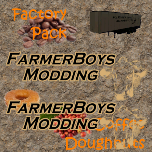
Version 08.04.23.00
1,903 downloads
Update 08.04.23 Added a utility trailer. Update 04.04.23 Added a drivable box truck. Walkthrough Video This pack requires downloading the Global Company Script from the in game modhub. Must be minimum version number 1.1.0.0 Important: A semi box trailer is included in the pack. This trailer must be used to pick up eggs and doughnuts. It can be found in tools/misc. This is a pack that includes 2 factory lines. A sell point, and storage building First is the coffee bean orchard, coffee bean roaster grow beans at the orchard and take them over to the roaster. Second is a doughnut production line. There is a mill that produces flour, sugar, and vegetable oil. A produce placeable that produces milk and eggs. Also very important is a semi box trailer that is included in the pack. This trailer must be used to pick up eggs and doughnts. The storage building will hold any product made or used in either factory line. wheat, barley, canola, corn, sunflower, soybean, sugarcane, sugarBeet, seeds, fertilizer, manure, coffeeBeanRaw, coffeeBean, doughnut, egg, flour, sugar, vegetableOil, milk, diesel, water, herbicide, and liquidFertilizer The sell point will only accept Coffee Bean Raw, Coffee Bean, Vegetable Oil, Flour, Sugar, Milk, Doughnut, Diesel, Fertilizer, Liquid Fertilizer, and Digestate Coffee Orchard Cost: 20,000 Input Percent Capacity Seed 5% 2.5 million Solid or Liquid Fertilizer 10% 5 million Herbicide 10% 5 million Water 75% 5 million Output Capacity Coffee Bean Raw 5 million Coffee Roaster Cost: 20,000 Input Percent Capacity Coffee Bean Raw 100% 5 million Diesel 5% 5 million Output Capacity Coffee Bean 5 million Farmer Boys Sell Station Cost: $1 Can sell Coffee Bean Raw, Coffee Bean, Vegetable Oil, Flour, Sugar, Milk, Doughnut, Diesel, Fertilizer, Liquid Fertilizer, and Digestate This placeable is found in the placeables miscellaneous tab. Factory Storage Cost: 10,000 Capacity: 50Mil per product Found in the placeables under silos. BD Produce Cost: 20,000 This placeable produces eggs from corn or wheat, and water. It also produces milk from barley, soybean, or sunflower. In addition manure is made as a by-product. To load eggs you need the Bd semi box van included in the pack. It can be found in tools/misc. Eggs are loaded up under the silo pipe. BD Mill Cost: 20,000 This placeable makes flour from barley or wheat, vegetable oil from canola, sunflower, or soybean, and sugar from corn, sugar beet, or sugar cane as well as diesel. BD Doughnut Fryer Cost: 20,000 This makes doughnuts from diesel, vegetable oil, flour, sugar, egg, milk, and water. To load doughnuts you need the Bd semi box van included in the pack. It can be found in tools/misc. Doughnuts can be loaded by the box on the end of the doughnut fryer. BD Semi Box Van Cost: 30,000 Has 2 options for capacity. 60K or 200K This trailer most importantly is needed to pickup eggs and doughnuts. It will also haul "ANY" material in the game. It will overload to seeders, sprayers, and refuel equipment as well. BD Semi Box Van W/Dolly Cost: 32,000 The same trailer and functions as the semi box van however there is a dolly fixed to the front so it can be pulled with a tractor or in tandem behind another trailer. This trailer also has an optional pin lock feature that allows you to keep the dolly from pivoting for easier backing.5 points -
NOTE: These scripts are personal edits of original scripts by various authors ( Stegei, Evgeny Zaitsev, Nicolas Wrobel,TracMax and W_R ) and posted on the FarmerBoysModding site for members of the FarmerBoysModding community's personal use and not intended for any general public release. Furthermore they are posted on the understanding that NO monetary gain whatsoever,regardless of source can be made from all or parts of them by any person(s). Including but not limited to, Patreon, soliciting for or requiring donations for work done for any purpose, posting on a website that gives any form of remuneration per download or view. Copyright remains with the original creators of these scripts. It would appear there has been some confusion with the new and old versions of these scripts so to avoid any confusion delete any previous versions of these scripts before installing these new versions and read the New Tutorials relevant to the script you are using. 24/05/23 --- Newer versions of some of these scripts available here Installation First a big thank you to Stegei, Evgeny Zaitsev, Nicolas Wrobel and TracMax the originators of some of these scripts. Whats New All the scripts no longer require the use of the Script Editor and are now executed directly from the script dropdown in GE ,- Select--Scripts The scripts now contain a set of Set Up scripts (Spline CSV Creator Set Up, Terrain Paint Set Up, Terrain Height Set Up and Spline Placement Transform ). These have to be run before using the main script as they create in the User Attributes panel of GE the User Attributes required for each script. They only require to be run once for each spline used whilst editing, also if the map is saved between edits the User Attributes created are also saved to the spline used so the setup script does not have to be run again when the map is opened for subsequent edits. Because of the various changes/updates to all the scripts it is recommended that all previous versions be deleted before installing the new versions. Download and unzip the Updated Spline Scripts.zip, and copy/paste the contents as laid out in the zip directly into C:\Users\Your Computer name\AppData\Local\GIANTS Editor 64bit 9.0.3\scripts The Updated Spline Scripts.Zip contains the following files, a brief description of each follows, further detailed information is contained in the relevant tutorials. Spline CSV Creator Set Up Creates in Giants Editor User Attributes Panel the User Attributes for the Spline CSV Creator script. Spline CSV Creator Creates a new Spline.i3d aligned to the terrain with the CSV distance set by the CSV Distance attribute in the User Attributes panel, also created is a Spline CSV data .txt both are placed in the new CSVdata folder created in the root folder of your map. Requires Spline CSV Creator Set Up to be executed first. Terrain Paint Set Up This script prints the terrain layer textures numerically in the Giants Editor Console log. It also creates in the Giants Editor User Attributes panel the necessary User Attributes for the Terrain Paint script operation.. Terrain Paint For painting along the spline using map terrain textures, different textures can be selectedand painted for the centre and left and right edge areas. Requires Terrain Paint Set Up to be executed first. Terrain Height Set Up Creates in the User Attributes panel of Giants Editor the necessary User Attributes for the Terrain Height script Terrain Height Allows for setting the terrain height using a spline and has independent height settings for centre width, left and right edge width. Requires Terrain Height Set Up to be executed first. Spline Placement Transform Creates a splineObjects transform group with the correct hierarchy in the Giants Editor Scenegraph and in User Attributes panel the User Attributes necessary for the operation of the Spline Placement script. Spline Placement Places objects along a spline at terrain height at fixed or random distances along/around and either side of the spline Requires Spline Placement Transform to be executed first Spline Placement Delete Deletes ALL objects in the placedObjects transform group. ----------------------------------------------------------------------------------------------------------------- Giants Editor Spline Scripts User Attributes Brief description of the various User Attribute settings, further information available in the relevant tutorial. Note: If the map is saved the User Attributes created will be saved (complete with settings) to the relevant Transform Group/Object and will be available when the map is reopened, as such to avoid complications with the save if any of the individual User Attributes are deleted (by selecting the red X) then the next time any of the scripts are run a warning will be printed in the Console log, example below \ WARNING\ ATTRIBUTES ERROR PLEASE RESELECT SPLINE PLACEMENT TRANSFORM The User Attributes will then have to be set up again by reselecting the named Set Up script in the above case the error is with the Spline Placement script Spline CSV Creator script User Attributes created after selecting Scripts-- Spline CSV Creator Set Up Terrain Height script User Attributes created after selecting Scripts—Terrain Height Set Up Terrain Paint script User Attributes created after selecting Scripts—Terrain Paint Set Up The letters in brackets on the left of each Attribute name are there to ensure correct layout if more than one set of spline attributes are set up on a single spline, the script name is also entered to separate the individual Script Attributes, example below. Spline Placement script This script isn’t affected by the multiple attributes problem (shown above) although it still uses the same spline as the rest the Attributes are assigned to the splinePlacementTransform not the spline itself. User Attributes created after selecting Scripts—Spline Placement Transform To avoid errors and having to repeat the various Set Up scripts it is advisable not to delete any of the User Attributes until work has finished using the particular spline after which they can be all deleted if required. Further information available from the tutorials Export a Spline from Giants Editor Into Blender to Create Roads/Railways (Updated) Terrain Height, Paint Terrain and Spline Placement scripts (Updated) Note: Before using any of these scripts on a current Work In Progress (WIP) map, it is recommended that a blank starter map is used to experiment and get familiar with the scripts, settings, executions and results. Read the New Tutorials as the operation and execution of all the scripts has changed. Updated Spline Scripts_18.12.2022.zip5 points
-
Version 2.9.19.1
344 downloads
This is a pack with modified Big Bud tractors. I added color selection to the tractors and the rims I added a second engine setup to both of them that adds both more hp and a bit more speed to them I also added compacting scale to them so they compact better than default ones do5 points -
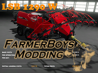
Version 30.12.18.00
3,476 downloads
Version 30.12.18.00 Kuhn LSB 1290 with added features. Main and secondary color selection: $200 Wheels color selection: $100 Base: No windrower $65,000 Work width: 2.75M Windrower: $2,000 Work width: 19M Work speed: 18mph Wheels: Default: $0 Wide: $200 Mud: $2005 points -
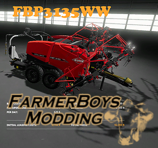
Version 01.01.19.03
2,208 downloads
Version 01.01.19.03 FBP3135 baler/wrapper with windrower option Base: $60,000 Work width: 3M Windrower: $2,000 Work width: 19M Work speed: 18mph Wheels Wide: $0 Narrow: $200 Narrow Dual: $200 Wrap colors added/full grid: $0 Base color: $200 Second color: $200 Wheel color: $100 Updated: 01/01/19 Version: 01.01.19.03 Sped up unloading and wrapping time. Wrap time is 6 sec instead of 15.5 points -
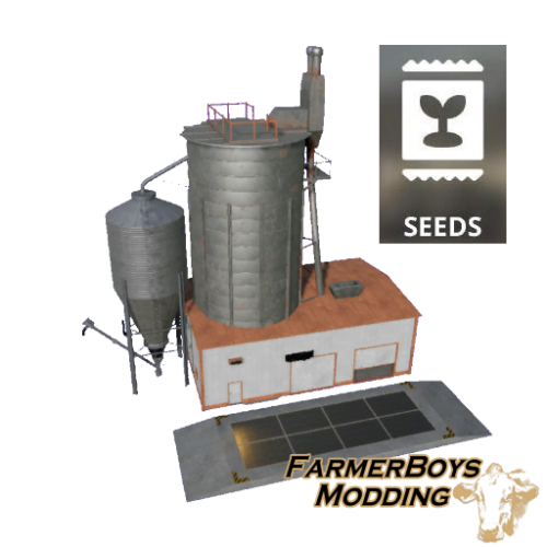
Version 21.10.19.00
733 downloads
This is a placeable seed production building. Its input and output capacities are 5 million. This pack requires downloading the Global Company Script from the ingame modhub. Cost: $20,000 Input: WHEAT BARLEY OAT CANOLA SUNFLOWER SOYBEAN MAIZE Output: SEEDS5 points -
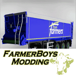
Version 1.0.0
414 downloads
Krampe from game reskinned . Higher capacity of 250k Faster unload Added a hitch to use with a dolly. This will only unload at the little graindoor, disabled the other unload option , otherwise with a dolly it would hit the trailer behind it.5 points -
Version 2.0.0
736 downloads
Multifruit harvester. 25kph/workspeed 200.000 capacity5 points -
NOTE: An updated version of the Spline CSV Creator Panels script is available here https://farmerboysmodding.com/index.php?/topic/2471-spline-csv-creator-panel-updated/ This new version creates a spline.obj file from the newly created spline for direct import into Blender without the need to convert from a .csv file This spline.obj will still need converting to a curve in Blender to create roads etc. There are two parts to this tutorial, the first part deals with creating a 2D spline in Giants Editor and using the Spline CSV Creator scripts to create a new spline aligned to the terrain with more cv's at a chosen set distance along it. Also created is a CSV (Comma Separated Variable ) file for use in Blender 2.79 (Only) to create a road mesh .i3d aligned to the map terrain. The following scripts are also used in this tutorial. Spline CSV Creator Set Up Terrain Paint Set Up, Terrain Paint Terrain Height Set Up Terrain Height The second part, the Blender section deals with creating a new mesh from the CSV data and using it to create a road layout i3d aligned to the terrain of your map for import into Giants Editor. Note: There is now an add on that imports the csv file directly into Blender see https://farmerboysmodding.com/index.php?/topic/2438-blender-plugin-300-and-above-for-splinecsv-data/ Whilst at first the tutorial may seem a little complicated once run through a couple of times it will seem quite easy. All the scripts used in this tutorial, together with the installation instructions are available here. 24/05/23 --- Link to newer versions of the scripts -- these versions do not require the separate setUp scripts https://farmerboysmodding.com/index.php?/topic/2439-new-spline-paint-height-csv-field-creationdimension-panel-scripts/ Link to original updated scripts https://farmerboysmodding.com/index.php?/topic/2412-updated-spline-csv-height-paint-place-scripts/ GIANTS EDITOR Spline CSV Creator Set Up Creates in the Giants Editor User Attributes panel the required User Attributes for the Spline CSV Creator The script is executed simply by Selecting –Scripts -- Spline CSV Creator Set Up in GE --and must be initiated before executing the Spline CSV Creator script. Spline CSV Creator Creates a new Spline_CSV.i3d from an existing spline aligned to the terrain with the CSV distance set by the CSV Distance attribute in the User Attributes panel, also created is a Spline_ CSV data .txt both are placed in the new CSVdata folder created In the root folder of your map. The CSV data is automatically converted from the Giants Editor transform axis to the Blender format, X(Z) axis, Y(X) axis, Z(Y) axis, (Giants in brackets) to use with the csv Importer script in Blender 2.79 The script allows for the original spline to be created in 2D with less cv’s and away from the terrain, the new spline created can easily be used in any of the Spline Height/Paint/ Placement scripts. Create a spline and align it to the road/rail network you wish to model, naming it accordingly. The spline can be called any name as long as it has the word spline in it i.e. road01_spline, spline_2 etc, the name chosen will also be the name of the spline.i3d and spline_CSVdata.txt created in the CSVdata folder in your map root folder. In Giants Editor --Select Scripts—Spline CSV Creator Set Up which will then create the User Attributes required by the Spline CSV Creator script a ‘ ‘SplineName’ CSV Creator Attributes Created ‘ message will appear in the consol log, then, Insert your map name in the (b).Map Name attribute The full name of your map ( root folder name) must be entered (Case Sensitive) in the (b). Map Name attribute in order for the CSVdata folder to be place in the correct position (map Root Folder) Insert the required value to the (c).CSV Distance attribute. The lower the number the more cv’s and greater accuracy in alignment in Blender or when used with the Spline Placement script In the example image below its set to 5, generally a value of 5 for roads and 10 or more for train tracks (gives a smoother incline) should be sufficient, but bear in mind that this distance will be the size of your individual road/rail sections in Blender. With the spline selected Select –Scripts --Spline CSV Creator A new Spline.i3d with your chosen Spline name will be placed in a newly created CSVdata folder in the map root folder along with a Spline_CSVdata.txt file. The message ‘New Spline: road01_spline_CSV.i3d and road01_CSVdata.txt created in Manor Farm / CSVdata Folder’ will also appear in the consol log, in this example the spline has been named road01_spline and map name is ‘Manor Farm. The new road01_spline.i3d can be imported directly into the map in GE by selecting File-Import and navigating to the map CSVdata folder in the map root folder and selecting the road01_spline_CSV.i3d which will then appear at the correct location in your map. The road01_CSVdata .txt is for use with the csv_importer script in Blender 2.79(only at the moment) and can be referenced in Blender directly from the CSVdata folder. The following image shows the Attributes and log messages created when selecting -- Spline CSV Creator Set Up Spline CSV Creator finally showing the imported road01_spline_CSV, note that the imported road01_spline_CSV translation is now set at 0,0,0 not at the road01_spline settings Setting Up the map Navigate to the CSVdata folder (in your map Root folder) and import the new --your name spline_CSV.i3d The next step is to paint the terrain along the road01_spline_CSV spline. Whilst this is not strictly necessary there are two reasons to do it, the first is to paint the terrain under any road mesh with a high AI value texture such as Asphalt or Gravel, although this probably won’t be seen, it means that an AI spline need not be created along any road mesh route not covered by the main traffic or AI splines, the second is purely for indication of road and edge size when setting the terrain height along this spline (settings should roughly reference to final Blender road width). It can also gives a performance advantage by allowing a lower clip distance on the road mesh without any visual loss when viewed from a distance. First Select—Scripts -- Terrain Paint Set Up this will create the User Attributes necessary for the Terrain Paint script and also print out the terrain layers textures in the Console log. In this example the Attributes have been sets as Set Centre Texture Width 5m Set Edge Texture Width 3m (both edges) Set Edge Texture Left 102 --see print out in Console Log for GRASS Set TextureCentre 98 --see print out in Console Log for ASPHALT Set Edge Texture Right 102 --see print out in Console Log for GRASS Set Distance Between Textures 0.5 --textures painted every 0.5m Select—Scripts-- Terrain Paint and the terrain will be painted with the chosen textures the following entry is printed out in the Console log detailing the settings. Spline Name : road01_spline _CSV Texture Left :- 93 -- GRASS Texture Centre :- 89 -- ASPHALT Texture Right :- 93 -- GRASS Centre Width : 5.0 m : Edge Width : 3.0 m : Texture Distance: 0.5 Result shown in following image. To ensure any new road mesh created using this CSV spline as a base fits the terrain it is necessary to provisionally adjust the terrain height along the length of the spline using the Terrain Height scripts. Terrain height may need to be adjusted when road mesh finally completed due to relaxing/smoothing of csv mesh. Before executing the Terrain Height script ensure that you save the map and make a backup copy of your map_dem.png in case of any problems. Select Scripts - Terrain Height Set Up This will create the necessary User Attributes used by the Terrain Height script. In the image above, the inset shows the original terrain profile with a sharp drop on the right hand side and raised terrain on the left hand side so the settings below have taken this into account this allows easier blending of either edge with GE terrain tools once the Terrain Height script has been executed. Also note that the Terrain Paint User Attributes are also shown the User Attributes window this is because the map was saved before the Terrain Height Set Up script was executed so the Terrain Paint User attributes were saved in the normal way and can still be used to adjust terrain textures using this road01_spline _CSV spline. User Attribute values, Set CentreWidth 6 (m) -- size dependant on final mesh size in Blender in this case a 6m roadbed with 2m Edges giving a 1m adjustment for final blending in GE after placement. Set SplineHeight 0 (m) --spline aligned to terrain Edge Transformation ‘selected’ --allows independent height and smoothing to either edge Set EdgeWidth 3 (m) 3m edge width either side of the CentreWidth Set Edge Height Left 4 (m) raises the left hand edge by 4m to match left hand terrain. Set Edge Height Right -4 (m) lowers right hand edge by-4m to match right hand terrain Set Edge Smooth Left 10 factors the amount of smoothing on the left hand edge Set Edge Smooth Right 10 factors the amount of smoothing on the right hand edge Select Scripts—Terrain Height The effects of these values are shown in the main window of the image above also printed in the Console log is a reference detailing the settings used together with the name of the spline, in this case Spline Name : road01_spline _CSV Offset:'True' Spline Height: 0.0 Centre Width: 7.0 m :Edge Width: 4.0 m : Height Left: 4 :Height Right: -4 : Smoothing Left: 8 Smoothing Right:8 Shown bottom right in the above image Further smoothing of the edge area can be made by reducing the EdgeWidth , HeightLeft and HeightRight by 1 and re executing the script until the EdgeWidth is ‘0’ (CentreWidth value not changed during this operation) Also note that the Terrain Paint User Attributes are also shown the User Attributes window this is because the map was saved before the Terrain Height Set Up script was executed . Note: Once executed this terrain deformation cannot normally be undone, but provided you haven’t saved the map after executing the script the terrain can be reset back to previous levels by selecting the Reload i3d in the toolbar( under the Create tab) then re adjusting script values as required. If the map has been saved then the only way of redoing the terrain is to Copy/Paste your backup map_dem.png into the map data folder. Once happy with the results save the map. NOTE: Before continuing see note at the beginning of the tutorial regarding update Spline CSV Panel script which now creates a spline.obj for direct import into BLender BLENDER 3.0.0 and above I have created a new plugin for Blender 3.0.0 and above which allows the SplineCSV data created in the Spline CSV Creator script to be directly imported into Blender instead of having to use an earlier version of Blender and exporting/importing as an obj which was previously necessary. Installation Download the spline_csv_importer.zip file available at the bottom of this topic. Open Blender (3.0.0 and above) Select –Edit—Preferences –Install and in the file browser navigate to where you saved the spline_csv_importer.zip file, Select and Install the Add-on. Once installed Activate it by selecting the check box (a single Left click usually brings up the Activation and Information panel) The Add-on can also be found in the Blender Preferences panel under Import-Export: Spline CSV Importer. Spline_CSV Importer Open Blender, Select File –Import – Import_Spline Data (*txt) a File Browser Panel will pop up. ( an undocumented operator panel appear but this can be ignored it just means I haven’t documented it with Blender) Navigate to where the CSVdata folder is (your map root folder), double click to open the folder and select the relevant spline_CSVdata.txt file, once selected, select the IMPORT CSV tab in the file browser. A new Collection in the Scene Collection Panel , SplineCSV will have been created and into that the new spline_CSVdata mesh (keeping your original name) will have been placed and the new spline_CSVdata mesh will also have been created in the same position in Blender as it was in your map ready for you to work with, the image below is for reference. All subsequent imports of Spline CSV data will be appended to the SplineCSV Collection retaining their original names Note: This Add-on will only create an single edge mesh (no other type of mesh) from a txt file created in the same format as the spline_CSVdata.txt file (i.e. no header), coordinates in the spline_CSVdata.tx have already been converted to the Blender format in the CSV Creator script and can be exported as an i3d or Nurbs curves directly back into Giants Editor. Blender 3.2 and above (other versions may differ in Menu’s and settings) Do NOT change the location of your mesh, if it is changed then problems will occur in placement when exporting final road mesh. (Quick way of getting the mesh in view is with the mesh selected, in the Collections panel, select decimal point on the Keypad) In Edit Mode ,with the mesh selected open the Tools Panel ‘N’ and select Edit – Loop Tools – Relax (arrow to left of word Relax) In the dropdown Interpolation –LinearInput Iterations ‘ 1 ‘ Note: High values will result in straightening out of curves Regular –Selected And select Relax This will relax the mesh giving a smoother line along the whole mesh. Change to Object Mode, with the mesh selected –Select , Object—Convert—Curve , this converts the mesh to a curve ready for use with the Curve Tools. Select the Curve Icon in the Scene panel (green semi circle) to open the Curve Tools Panel With the curve still selected change to Edit Mode The new curve first needs to be aligned along the correct axis for the road, to do this you can either select Control Points—Tilt and type 90 or simply (Ctrl ) -- T -- 90 In the Shape panel of the Curve Tools, select 3D, Fill Mode 'Half', Curve Deform 'Radius Selected', all other settings can be left as is. Open the Geometry and Bevel Tabs Geometry Tab Extrude ‘ 3 ‘ ---this equates to a road bed width of 6 metres , half the desired width Offset ‘ 0 ‘ ---value can be left at 0 as this just raises or lowers the mesh by +-1m Bevel Tab Select -- Profile Depth ‘ 2 ’ -- this figure is the width of the road edges in metres, in this case 2 for 2m Resoloution – ‘ 0 ’ --This figure sets the number of subdivisions in the edge mesh should you wish to create your own custom or preset profile. You will note that after entering the figure in the Depth box the curve point of origin is now aligned to the bottom of the edges, this change will need to be catered for when the mesh is finally imported into GE. The following image shows the result of these transformations. Once you are happy with the basic shape, the curve deformations can now be turned into an editable mesh. With the curve selected Object Mode – Object –Convert --- Mesh The mesh can now be edited in the normal way for example adjusting the bends in the road to be smoother and adding white lines (see Enhancements at the end of the tutorial). Texture Add the texture you are going to use in the normal way One quick method I use is in the example below, Edit mode –with all the road bed faces selected UV –Reset -- adjust the UV map to fit the road bed texture (inset 1 shows full road texture ) Do the same for each of the road edges then, Edit Mode—Edge Select – and select both outside road edges and raise to a shallower angle (inset 2) Finally Export as an i3d either using the .blend filename or creating your own in File Location Open your map in GE and import the road mesh i3d (in this case it is road01_splineCSV) Rotate the ‘Y’ axis by -90 and adjust the ‘Y’ Translation of the road mesh to match the flattened terrain. Further adjustments (texturing/terrain height) of the road area can now be carried out. The image below shows the road imported and adjusted, the inset shows a magnified image of the road placement at the indicated location. Note: To enable the AI to work better with the new road mesh, the Collision Mask (Hex) should be set up as follows, Where 0: "DEFAULT: The default bit", 1: "STATIC_WORLD: Collision with terrain, terrainHeight and static objects", 2: "STATIC_WORLD_WITHOUT_DELTA: Deprecated in FS22: Do not use it anymore!", 3: "STATIC_OBJECTS: Collision with static objects", 4: "STATIC_OBJECT: A static object", Deselected is 5: "AI_BLOCKING: Blocks the AI", 6: "TRACTOR: Deprecated in FS22: Do not use it anymore!", 7: "COMBINE: Deprecated in FS22: Do not use it anymore!", 18: "AI_DRIVABLE: AI can drive over this node", The above settings are taken from the base game road mesh , although numbers 2,6, and 7 state that they are no longer used it would be prudent to include them anyway as the collision masks may have changed in later game patches. ENHANCEMENTS Adjusting and smoothing blocky curves/bends Example; Navigate to a curve section you want to adjust in the viewport Edit Mode Select the outer edges of the road sections in the bend (3 in this case) and subdivide, number of subdivisions will be dependent on smoothness required. Open the Tools Panel ‘N’ and select Edit – Loop Tools – Relax (arrow to left of word Relax) In the dropdown Interpolation –Linear- Projects vertices on straight line, Cubic uses a natural cubic spline to project the vertices Input – Parallel (all) --This will also modify any parallel vertices at the same time, if in doubt select, Section, only selected modified. Iterations ‘ 1 ‘ – No of times tool is run, higher number gives smoother results but straightens out the curve Regular –Selected –When selected vertices spread evenly along the loop Select the vertices along the edge of the curve Section, and select Relax Further smoothing can be carried out by repeating the above process on the relevant section Finally select all the vertices along one edge of the whole road mesh and then select Relax This will smooth out the whole road mesh Image below shows the various stages and images 1 and 3 show the before and after result. Adding Custom road markings. Select all the road bed faces (Shift-Alt held - select face) of your finished road mesh, change to Edge select, again with Shift-Alt held deselect left and right hand edges and Subdivide ' 1 '. Select the new centre edge (Shift-Alt held - select edge) and Shift-D to copy ' P ' Selection to separate from main road mesh, with the new edge mesh selected Object mode – Object--Convert--Curve Curve Tools panel --Shape-- Geometry and set Extrude to ‘ 0.2 ‘ (Extrude value dependent on the width of the road marking texture used) Edit mode Ctrl 'T ' -90 to correct the axis. Object mode -- Object--Convert--Mesh Add texture as normal not forgetting alpha channel settings in Blender Edit mode -Face select --select all UV—Reset -- adjust UV mesh to fit texture Texture may need to be adjust on the bends but that is easily done in the UV editing window Finally when satisfied export as i3d. To do the edge markings (if required), select the left hand or right hand edge and Shift-D to copy ' P ' Selection to separate from main road mesh and continue as above, doing the same for the other edge. Example below The previous tutorial showed two ways of creating the road mesh from the CSV mesh but I think the above method is the quickest and easiest way to get the best results. As it is possible to create a spline in Blender 3.2 and export it as an i3d you can create a set of splines aligned to the road mesh to use in the Spline Placement script and also for traffic/railway splines Using the finished road mesh as an example For Spline Placement In Edit mode, Edge Select Shift-Alt select the left or right hand road edge so all the edges are selected. Shift ‘ D ‘ to copy With the edge still selected ‘ P ‘ Selection to separate Object Mode With the edge selected -- Object –Convert—Curve Edit Mode Curve –Set Spline Type – NURBS Object mode Open i3d exporter Export Tab and ensure that Nurbs Curves and Shapes are selected Set up filename and File Location in the Output tab Export the i3d Import into map set ‘ Y ‘ rotation to -90 and Edit-- Freeze Transformation –Rotate Only (leave preserve instances selected) height settings do not matter as objects will be placed on the terrain at their point of origin. Replace any splines in the splinePlacement transform with this new spline and set up the script parameters accordingly. Example before selecting Object mode and exporting For traffic/railway splines Select all the road bed faces (Shift-Alt held - select face) of your finished road mesh, change to Edge select, again with Shift-Alt held deselect left and right hand edges and Subdivide '3 '. If creating a railroad spline then Subdivide ' 1 ' Subdivide ‘ 3’ is necessary to get the correct location for the traffic splines (midway between centre and edge). The centre edge line can be used, if required, as a new roadSpline01_CSV to adjust any terrain height after smoothing of road mesh (slight straightening of bends etc). Shift-Alt select edge to the left of the centre of the road mesh so all the edges are selected and continue as above for the splineUtilsPlace adding a further step after the ‘With the edge still selected ‘ P ‘ Selection to separate’ of renaming the mesh to traffic01_left for clarity and continue the method above. Repeat the procedure for the right hand edge. Image showing both sets of splines. Once the traffic splines are imported the Translation/Rotation needs to be set up as follows Translate ‘ X ‘ and ‘ Z ‘ to‘ 0 ‘ Translate ‘Y ‘ to a suitable value to align it just above the road mesh, in this case -1.9 Rotate ‘ X ‘ and ‘ Z ‘ to ‘ 0 ‘ Rotate ‘Y ‘ to -90 Once done freeze (Edit-Freeze Transformation) the Transformation/Rotation settings. As both traffic splines, after importing are in the same direction, traffic direction can be set by selecting the relevant spline and pressing the ‘ R ‘ key on your keyboard. All the splines once imported into the map can be edited/ expanded in the normal way. Note: Regardless of the filename you have given the spline in Blender the name in the scenegraph of GE will be the name in the Collections Panel of Blender with the suffix.001 in this case road01_splineCSV.001 Below is an example showing the road mesh, markings, together with the various splines and also objects that have been placed using the Spline Placement script (see Terrain Height, Paint Terrain and Spline Placement scripts (Updated) for details of placement). spline_csv_importer.zip4 points
-
Version 10.04.20.00
1,685 downloads
Version 10.04.20.00 Decal fixes Version 07.10.19.00 Handling update Huge thanks to Grabby La Toosh for testing and sharing suggestions. He also did some motor and suspension work. Im sure im missing more. Bigger thanks to NcRaiders for extensive xml help, most of all fixing everything i kept breaking in the xml. I couldn't have finished this guy without both of their help. This is the Imperador 3.0 with some cool features. The machine sprays liquid fertilizer and herbicide like the default machine, however rather than just spreading fertilizer, it will spread lime as well(at a wider work width). Base cost: $165,000 Capacity: 10K liquid (herbicide liquid fertilizer) 10K solid (fertilizer lime) Work width: Liquid: 27M Solid: 42M Drive speed: 70mph Work Speed 18mph Color selectable Motor: Base 350HP $0 450Hp $3,000 550Hp $6,000 650Hp $12,000 750Hp $ 18,000 Wheel Base Narrow $0 Medium $1,000 Narrow Dual $2,000 Medium Dual $3,000 Monster Dual $6,0004 points -
Version 1.0.0
550 downloads
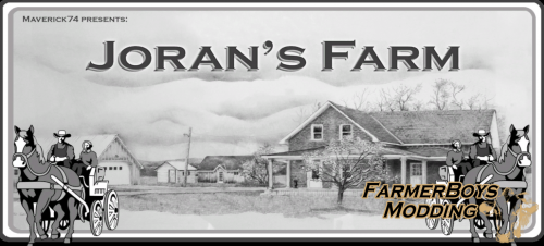
Why the name Joran’s Farm? Joran was a 14 year old kid who was a huge fan of my first map. He dreamed of having his own map and to learn modding himself. He was a very friendly and a smart kid who was fighting cancer. I started to work with him and we had daily contact. I started to create a map for him with his name. Some of the items on this map he created or reskinned himself. Most things and play-style on this map were his idea. Sadly he lost his fight against cancer 28 May 2018. I made the landing point on the map into a memorial for Joran. Please take a look and hold a minute of silence for him. This map requires mods that are not included with the map. You can find the mods that are required for the map to function properly here. Required Mods4 points -
Version 20.06.20.00
567 downloads
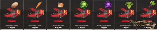
Varitron 960 In game 470 with some added bells and whistles. This unit will harvest potato and sugar beet. Just be sure to look in the potato or sugar beet category. Added a wide header option, capacities, motor selection, and several color options Work speed: 12mph/19kph Hp: 435 or 1000 Work width: 3m or 9.6m Capacity: 20k, 50K, or 500K Base, design, and rim color selections.4 points -
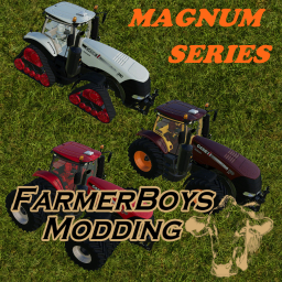
Version 06.10.19.00
807 downloads
This is the in game Magnum series with some upgrades. Extra power, 4 crawlers, triples, & more. Base Price: $50,000 Base Color: $100 Design Color: $50 Motor Speed: 75mph 340 CVX 500HP: $0 380 CVX 1000HP: $5,000 Wheel Selection: Rim Color: $100 All 4 Crawlers: $10,000 Default: $0 Wheel Weight: $1,200 Broad Tires: $2,000 Broad W/Weights: $3,000 Twin Narrow: $2,000 Twin All: $5,000 Twin Rear: $4,000 Triples: $6,0004 points -
Version 1.0.0
311 downloads
Modified Scorpion. Able to cut trees up to 20 meter . Faster driver speed ,more power.4 points -
Version 25.10.23.01
426 downloads
Update 25.10.23.01 Registered cotton as bulk so tippers taking bulk will haul cotton, silo accepts cotton along with cotton bales. Update 16.01.23.01 PLEASE READ If you have Silage additive in this silo please move it to another location before update or you will lose it. I added silage additive to a category so that there wouldn't be a need for 4 triggers. I added a second unloading point like I did to the fermenter silo to help with auto drive issues and trailers that may load multiple products. Update version 04.11.22.01 added bale trigger for silage, hay, straw, grass, quick bale deletion too. Update version 09.01.22.01 added refuel trigger for equipment. Update version 31.12.21.01 enlarged liquid triggers, added silage additive to storage. This placeable silo will accept anything. Solid and Liquid. (I left grapes out for now, it was causing huge lag on my system when unloading/loading them, if requested I can do a private edit, its simply adding trainwagon in to the categories.) I suggest you have an even area to place it. If you are having issues finding a trailer that will hual and load with all liquids check out my FERMENTER PACK it has the in game MK8 edited to haul all liquids and it will transfer as well as fuel equipment. I have also added the small saddle tank and a service trailer to that pack.3 points -
This script can be used to easily place fences/power lines on a map using a spline. It consists of a basic spline placement script and a modified easyFence script (by modelleicher) combined with some extra enhancements. The script works by first placing posts/poles aligned to the terrain along a spline, it then places fence boards/wires on these posts/poles scaling them to match the distance to the next post/pole. To install download the script (available at the end of this tutorial) unzip the fencePowerPlacement.zip and Copy/Paste the script into C:\Users\Your Computer Name\AppData\Local\GIANTS Editor 64bit 9.0.4\scripts. Once installed, to initiate the script select the Fence Power Placement script in the GE Scripts tab. A panel will pop up somewhere on the screen. The image below shows the Panel, together with a brief description of the Inputs/Parameters Points to Note before using this script. All posts/poles/wires/boards Must be scaled at 0,0,0 before use in the script Items to be placed Must be aligned along their ‘Z’ axis with the point of origin at one end. Number of Wire/Board alignment nodes Must be the same on all posts/poles used and in the same order top to bottom otherwise you will have crossovers between the posts. The post/pole transform group hierarchy must always start with the post mesh followed by the wire/board alignment nodes it can then be followed by any other meshes although I think best practice would be to have a single mesh for the pole/post including all the parts. The following image shows the transform group hierarchy and the telegraphPost placed using the script Above Telegraph pole taken from the FS19_telegraph pole kit by Robbie available on modhub Placing a Simple Fence Simple post, fence board creation For this example I will create a simple post/board using the Create- Primitive - Cube in GE The finished fence will consist of square posts and three fence boards If you already have a suitably aligned post and fence board then skip the next section, import post and fence wire/board into GE and go to Adding the alignment nodes to a post. section. If not continue with the following, In GE Create - Primitive - cube In the attributes panel Translate 'Y' enter 0.5 also rename this post_1 Select Edit - Freeze Transformations and select Translate - this will move the cubes point of origin to the base of the cube In the attributes panel enter the following into the Scale transforms 'X' 0.15 , ‘Y’ 1.5, 'Z' 0.15 and Freeze transformation Scale (only Scale ensure all others boxes are deselected) In the material panel in Albedo Colour enter 0.4, 0.2, 0.2 this will give a brownish colour to the post Create a second cube In the attributes panel Translate 'Z' enter 0.5 and rename this to board_1. Select Edit - Freeze Transformations and select Translate - this will move the cubes point of origin to edge of the cube In the attributes panel enter the following into the Scale transforms Scale 'X' 0.1, 'Y 0.2 'Z' 4 and Freeze Transformation Scale (only Scale ensure all others boxes are deselected) Because this second cube still uses the material name ‘Unnamed material’ it will be the same colour as the post. Create a new transform group and name this fencePowerItems Select post_1 with the middle mouse button and keeping the middle mouse button pressed move post_1 into the fencePowerItems transform group, do the same with board_1. The reason for this is to keep the transforms all set to 0,0,0, which will prevent any unseen conflicts with translation positions. With the fencePowerItems transform selected on the keyboard select Ctrl B to place it in your current view port for reference. Adding the alignment nodes to a post. Create a new transform group –Create – Transform Group Select the new transform group with the middle mouse button and keeping the middle mouse button pressed move the new transform group into the post_1 transform. If you do not have a middle mouse button then cut/paste the new transform into the post transform. Next move the new transform up to where you want the lowest board to be With the new transform selected on the keyboard select Ctrl D to duplicate then move this second transform to the centre board position, repeat this step for the third transform placing it where the top board will be. Your post_1 alignment transforms should look like the post in the alignment image above. Your post transform should look like the following image Open your map in GE Create a spline – Create- Spline rename to spline_1 and align it along the route you want to place your fence. Select Scripts – Fence Power placement to initiate the script. In the Scenegraph a new transform group ‘fence_powerObjects’ will have been created consisting of three transform groups wire_fenceNode – place the fence board(s), wire(s) in this transform group fencePlacement Transform Group postObject – place your post(s)/ pole(s) in this group placedObjects – your complete fence/power line will be placed in this group when the script has been executed (select Create Fence/Power Line) The spline has to be placed in the fencePlacement Transform Group For those familiar with the original Spline Placement script this fencePlacement Transform Group works in the same way as the Spline Placement script. I have renamed the post_1 and board_1 meshes to post1S1,board_1S1 (S1 being spline_1) respectively. Unfortunately GE will scale all objects of the same name throughout the map so I have done this so that I can easily freeze the scale transformations on the completed fence/power line without affecting any other mesh in the map. Copy/Paste board_1 into the wire_fenceNode transform (rename if you want to). Copy/Paste post_1 into the postObject transform. (rename if you want to). Cut/Paste the spline into the fencePlacement transform Set Post Distance – 4 – posts will be set 4m apart Stay Upright – Selected – this will ensure the posts remain upright regardless of terrain contour Select Random Spline Order – Deselected – this will be used in a later section of the tutorial Select Random Wire/Board Placement – Deselected -- this will be used in a later section of the tutorial No of Wire/Board Nodes – 3 – this is the number of transform nodes on the post Maximum Posts – 0 – Default setting means all post will be used Start Post – 0 – default setting script will start at first post Remove Current Fence/Power Placement – Deselected With the fencePlacement transform Selected, Select the Create Fence/ Power Line button The fencePlacement transform must be selected for the script to run. In following image ‘Image 1’ shows the renamed post_1 and board_1 in their correct transform groups together with the spline in its correct position and the Fence/Power Placement Panel ready for input. Image 2 shows the Fence/Power Placement Panel with all the relevant data entered and the script executed by selecting Create Fence/ Power Line button Image 3 shows another view of the placed fence and the two other insets shoe the difference between Selecting/Deselecting the Stay Upright parameter You can check out the difference between the Stay Upright modes by, Remove Current Fence/Power Placement –Select – this will delete the current fence placement Stay Upright – Deselected Remove Current Fence/Power Placement –Deselect – Important step otherwise new placement will not take place Select -- Create Fence/ Power Line button – this will create the same fence placement but with the posts following the terrain contour To return to the original placement, Remove Current Fence/Power Placement –Select Stay Upright – Selected Remove Current Fence/Power Placement –Deselect – Important step otherwise new placement will not take place Select -- Create Fence/ Power Line button The Remove Current Fence/Power Placement selection can be used to delete an existing placement and add/change any parameter then execute the script with the new settings. For wire placement the alignment method is slightly different in that the transform nodes are placed on the outside of the post on the ‘X’ face. Although normally a fence post created for wire would already have the staples (the staples would have to be on the ‘X’ face of the post) as an integral part of the post mesh. Random Post/Board Placement For this example I have created a shiny round post by, Create – Primitive – Cylinder Rename – post_2 Translate ‘Y’ – 0.5 Freeze Transform Translate Scale X 0.2, Y 2, Z 0.2 Freeze Transform Scale Albedo Color 0.8,0.8,0.8, Smoothness 1 Metalness 1 Cut Paste into fencePowerItems Transform For the boards I have just duplicated board_1 twice renamed board _2, board _3 respectively and scaled X,Y values (not Z as this is the distance between posts) then Freeze Transformed scale on the new boards Ctrl B the new fencePower Items to your map location The alignment nodes on the post are set up the same way as for the post_1 (must be the same number) Copy/Paste board_2,3 into wire_fenceNodes Copy/Paste post_2 – into the postObject transform Using the same spline the script set up is as follows Set Post Distance – 4 – posts will be set 4m apart Stay Upright – Selected Select Random Spline Order –Selected Select Random Wire/Board Placement – Selected No of Wire/Board Nodes – 3 – this is the number of transform nodes on the post Maximum Posts – 0 – Default setting means all post will be used Start Post – 0 – default setting script will start at first post Remove Current Fence/Power Placement – Deselected With the fencePlacement transform Selected, Select the Create Fence/ Power Line button The image below shows the Script parameters and random placement of both the posts and boards If you want to create some missing fence boards add another empty transform group to the wire_FenceNode transform group. The odd posts are deliberate to highlight the effect of the random spline placement Power Lines I will be using some premade power pole and wires for this example An example of a power pole with multiple objects is shown in the Points to Note before using this script section at the beginning of this tutorial The alignment node set up method is slightly different for the power poles. Create a transform group and Select the new transform group with the middle mouse button and keeping the middle mouse button pressed move the new transform group into the powerPole transform group. With the new transform node selected, hover the mouse over the insulator you want to hold one of the wires, then Ctrl B left click twice to place it on the insulator Do the same for all the other insulators Image below shows the placement of Power Lines together with the relevant script settings, inset gives a clearer picture of the placement Below Power Placement using the Select Random Wire/Board Placement with an extra saggy wire (wireSag2) randomly placed again inset shows clearer placement Finally using the script twice to place power Lines and a damaged barbed wire fence Further Notes Wire_FenceNode objects must be single meshes and not part of any transform group. There is no limit on the no of items that can be placed in either the wire_FenceNode or the postObject node the only stipulation on extra posts is that they must all have the same number of alignment nodes. Post/poles must also be single meshes and not part of any transform group. The alignment nodes on any post/pole must be the first children of that mesh, however other meshes can be placed after the alignment nodes for example Though currently if using a tree it will only be placed in one rotation and LOD1 is not supported. You can of course manually place a tree in place of a post by first selecting the post in the viewport and then in the scenegraph copy the three transform nodes of that post. Using the replace function select the post as the Target and the tree in the Replace With section and select Replace, align the tree with the end of the previous posts wires and with the tree transform group selected paste the original 3 transform copied previously into it The following image shows the result of this method Error Messages Error messages will appear in the console log if, Nothing is in the wire_FenceNode transform group Nothing is in the postObjects transform group Incorrect number of transform alignment nodes on a postObject item error message and name object will be printed in the log Spline is in the wrong transform group or not present in the fencePlacement transform Group When the script has finished the following will be printed in the log Finished! Enjoy the fence 🙂 Spline Name: (name of spline) As normal I suggest you try this script out on a test map before using on any WIP map also this script is still being developed so may change at a later date. Original Easy Fence script available here select all and paste into new notepad++ file and save as easyFence.lua. https://pastebin.com/1DR6qDcE Damaged barbed wire/poles taken from FS 19 Barbed wire fence kit by Robbie https://www.farming-simulator.com/mod.php?mod_id=105801 Fence_Power_Placement.zip3 points
-
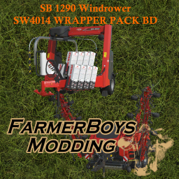
Version 07.12.22.00
656 downloads
Live Updates 07.12.22.00 After converting the Nova Cat mowers I decided to add the option to remove windrowers on the baler. Just a heads up the first time you load you game save with an old baler on the map it will give you a warning about config settings (I added), however once you save the game and re open the warning will no longer be there. 1 (31).mp4 1 (32).mp4 02.11.22.01 Added a hitch to the baler and added a sped up wrapper. If you had the sb1290 bought it will by default now have the hitch, if you don't want the hitch you can upgrade it in the shop to remove it. Again in the shop default is with the draw bar, it is an option to remove it. The wrapper in the pack can either be found by hitting the combination under the baler or simply look for the modded Kuhn 4014. 31.12.21.01 Now live, added sounds for windrow arms. 29.12.21.01 Added siliage additive option (gives you a 5% boost in yield with grass only) 27.12.21.02 Removed light in i3d causing warning This is the SB 1290 (square) baler with some bd upgrades. Simply it has windrowers added to it to widen your work area to 20 meter. Also has the option for silage additive. Silage additive adds 5% yield to grass only. Again please give me feedback and I hope you enjoy.3 points -
Version 09.02.23.01
409 downloads
Update Version 09.02.23.01 Upped output speed and added some language translations. Update Version 17.01.23.01 Moved liquid loading trigger to the side, updated icons. Update Version 04.11.22.01 Sped up bale deletion. Update Version 03.11.22.01 Added bale trigger to input. I changed the leveling area but it is suggested to have a larger area or level an area out before placing. This building makes seed with barley, wheat, oat, soybean, corn and it will also need a small amount of fertilizer with each line. This building also makes lime from stone. This building also makes fertilizer and digestate from silage. TO USE PRODUCTION To get to productions hit P and go down to the dashed lines then select construction, then production. If you have no other production mods it will be all the way to the right and named fermenter. Once you put material in the silo you will need to activate the production. To do this hit escape and click on the production icon, i believe its right under contracts. Then you simply select each line and hit activate on the bottom.3 points -
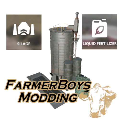
Version 09.09.19.01
1,410 downloads
This pack contains the following fermenters. Each fermenter has an input and output capacity of 5 million. This pack requires downloading the Global Company Script from the ingame modhub. Silage Solid Fertilizer Fuel Liquid Fertilizer Cost of each building: $20,000 Input: GRASS WOODCHIPS CHAFF HAY STRAW (takes bales as well) Output: Every building outputs silage and per name of building.3 points -
Shywizard did this awesome video, I wanted to be sure to share it here so he doesn't have to use his personal file space. 2020-12-07_18-38-39.mp43 points
-
I know I helped with beast so I’m bias but this thing is a blast. Stumps are simply pooof. Drop machine in front of the tree, cut, then run the stump over. Quickly trees are chips and stumps are dust. Huge thanks to NC for taking on this challenge.3 points
-
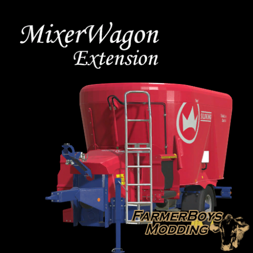
Version 1.0.0
400 downloads
You have to put this mod in your modfolder to get the modded MixerWagons to work correctly. Without this the output will still be forage.3 points -
Version 02.11.19.00
584 downloads
Supply this placeable with diesel and it will deliver lime to the silo. 1L of diesel outputs 200L lime. This placeable requires downloading the Global Company Script from the in game modhub. Cost: 20,000 Diesel Capacity: 250K L Lime Capacity: 5 Million L3 points -
still working hard on the fs19 map , i have no release date.3 points
-
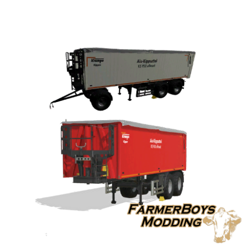
Version 01.10.19.00
1,130 downloads
KS950 Pack <version>01.10.19.00</version> Added high capacity option <version>19.02.19.00</version> Updated mod and store image. <version>19.02.19.00</version> Worked on drawbar (visual purposes), fixed connections on front (now show before connection). This is the KS950 Krampe trailer modded a bit. I added a second trailer with a dolly attached so the unit could be used as a road train. The dolly has a pin lock option to help with backing up. I also found a new cool feature. I was able to make decals colorable. KS950 Price: 55,000 Colorable: Chrome, Stainless, Full color grid. Decal Colorable Chrome, Stainless, Full color grid. Rims Colorable: Chrome, Stainless, Full color grid. Wheels Wide or Dual Capacity: 60,000 High Capacity: 200,000 ($3,500) Rear Hitch KS950D (has a built in dolly with an option of a pin lock system, works with the default fold buttons) Price: 62,000 Colorable: Chrome, Stainless, Full color grid. Decal Colorable Chrome, Stainless, Full color grid. Rims Colorable: Chrome, Stainless, Full color grid. Wheels Wide or Dual Capacity: 60,000 Rear Hitch3 points -
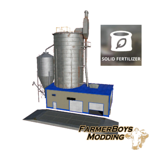
Version 19.09.19.00
690 downloads
This is a placeable fertilizer production building. Its input and output capacities are 5 million. This pack requires downloading the Global Company Script from the ingame modhub. Cost: $20,000 Input: SILAGE MANURE LIQUID MANURE DIGESTATE STRAW (takes bales as well) Output: FERTILIZER3 points -
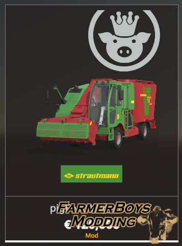
Version 1.0.0
271 downloads
This are edited strautmann foodmixers. Includes - pigfoodmixer = Mix corn 50% , wheat 25% , canola 20% and potato 5% to make pigFood. 75k capacity colorable. (You need to put the FS19_MixerWagonXT mod in your modfolder to get this to work correctly, made by ThundrR75) -foragemixer 75k capacity colorable3 points -
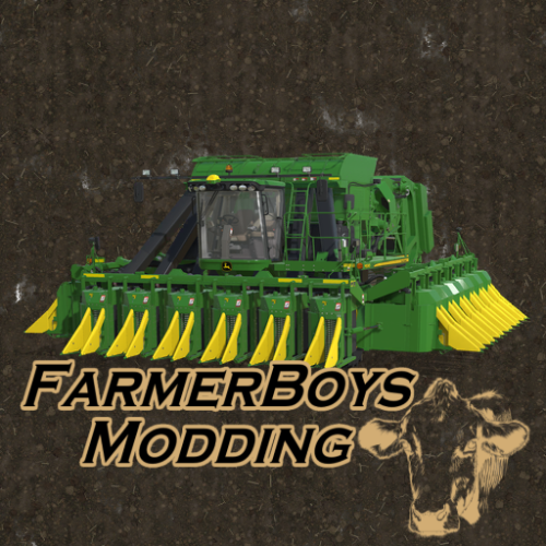
Version 06.03.24.01
223 downloads
Update 06.03.24.01 minor i3d change Update 18.06.23.01 fixed AI/worker working width. Thank you Soas77(Iamjob) for catching this. Sorry for the inconvenience. Update 10.05.23.01 Sped up bale unloading by 4x and fixed issues with the bale not dropping to the ground. Please let me know if you have any issues with bale unloading. Update 07.05.23.01 Added Rivet and decals to the wings, reworked the dirt. This is the John Deere CP690 cotton harvester with an added foldable header, sped up, motor upgrade, and color options. I will add a usage video soon. Once the unit is unfolded you can unfold and fold the header with the lift/lower button.2 points -
Create Field Dimensions and Farmlands Tutorial This tutorial will endeavour to show you how to create field dimensions, paint the farmland area (InfoLayer_farmlands.grle) and automatically add the relevant farmland entries in the farmland.xml together with painting your chosen Ground Type (i.e Plowed,Cultivated etc) and painting foliage at a chosen growing state on the chosen field using custom scripts. For clarity the abbreviation TG will be used to denote a Transform Group throughout this tutorial. I would like to thank Modelleicher for allowing me to use and giving permission to slightly modify the following scripts in this tutorial in order to add some extra functions. Create Field Dimension Panel Creates field dimensions from markers Paint_Farmland_Field_ID_Panel Paints the InfoLayer farmlands.grle and adds relevant data to the farmlands.xml. Paint Field Ground Foliage Panel Paints the chosen Ground Type (i.e.Plowed,Cultivated etc) and Foliage at a chosen state (i.e. wheat, harvest ready). All scripts are available in the Field Dimensions and Farmlands zip file available at the end of the tutorial. Also have a look at the following youTube videos by Modelleicher on the creation of the original scripts and for a master class on script creation. https://www.youtube.com/watch?v=jLL7x064mJc --Field Dimensions https://www.youtube.com/watch?v=QhCOBkOxjPE –Paint Farmlands https://www.youtube.com/watch?v=dxnZI8C02NY --Farmlands.xml Create Field Dimensions, Create Farmlands and Paint Ground and Foliage on the field The three scripts used for this are the Create Field Dimension Panel, Create Farmlands Panel and the Paint Field Ground Foliage Panel. The Paint Field Ground Foliage Panel script now automatically reads the Foliage Type, Ground Type, Ground Angle, Spray Type associated with your map from the map.i3d and displays it in a dropdown selection. However the Foliage State for each Foliage Type still requires a number value (position in the Layer State dropdown in GE) To assist with this the script now reads all the Foliage States of each Foliage Type directly from the maps foliage folder xml’s and prints result to the console log and to a foliage_States.txt file in the same folder as the map.i3d for easy reference, the image below shows the extracts from console log print out and the foliage_States.txt file . The foliage states listed here are from a test map based on the US map so yours may differ depending on your map set up. Open your map in Giants Editor and Select –Scripts, select the Field Dimensions and Farmlands folder to open it and then select the Create Field Dimension Panel script a popup Panel will appear on your screen. A new transform Group will automatically have been created in the Scenegraph called Field_Creation_Transform consisting of the following TG groups newFieldMarkers – this TG will be the the reference point for the fieldMapIndicator and also contains the Markers transform where the markers are placed. fieldsNew -- containing a fields transform although this will have the FieldUtil.onCreate attribute set by the script I suggest deleting the attributes and reassigning them by Add New Attribute --Type --scriptcallback -- onCreate -- Add and in the new onCreate box enter FieldUtil.onCreate as some times GE doesn't recognise some script set User Attributes. This only applies to the field TG in the fieldsNew TG. The relevant entries created in this fields TG must be copy/pasted in to the gameplay –fields TG replacing originals before using in game farmlandDimensions -- containing a fields TG with the FieldUtil.onCreate attribute set. This will be used in the creation of the farmlandsDimensions Create a primitive (Create –Primitives, I will be using a cone throughout this tutorial.) and cut/paste into the newFieldMarkers transform (this will be the position of your fieldMapIndicator in the new fields TG). Copy/paste a cone into the Markers TG Your Scenegraph should now look like this. If you haven’t already got an outline of your proposed field area then I suggest you make one using the Terrain Detail Texture Mode and a suitable texture. Once you have a field border then CTRL ‘B’ the newFieldMarkers transform into the field area. Note: The newFieldMarkers transform MUST be placed in a position that allows ALL the field boundary to be seen from that position (the cone in the newFieldMarkers TG will provide a reference point) otherwise the script will not work correctly, so for complicated field shapes you will have to create the fieldDimensions manually or by using FieldDimensionsWithBitmap script available from here https://ls-modcompany.com/forum/thread/5852-fs19-ge-script-fielddimensions-per-bitmap/ Also the Markers (cones) must be in a consecutive order, so if you have to add any additional markers to your layout (after creating one) then the extra marker must be placed in between existing ones in the Markers TG as the script uses each marker in turn to create the field Dimensions. Place the ‘cones’ along the edge of the field by CTRL ‘D’ (copy existing cone)-CTRL ‘B’ (place new cone) at suitable points as shown in the following image ( I have scaled the cones up for better definition). Using the fields transform in the fieldsNew TG to create the new field dimensions. In the Enter Field Number box enter the field number you want for this field. Now, first selecting the fields transform and holding Ctrl key select the Markers transform, releasing the Ctrl key and select the Create Field Dimension button. The new field dimensions together with the fieldMapIndicator will be created in the fields TG in the fieldsNew TG, if they are not visible in GE then with the fields TG selected Select – Scripts – Map –Toggle Render Field Areas and they should appear in GE. A Created Field Dimension for Field ‘field01’ message will also appear in the console log (field number will change to field created in subsequent operations). Results shown in following image. The script sets the default for fieldGrassMissions and fieldMissionAllowed to false. To change this to your prefered setting select the field number transform (field01 in the folowing image) And select the relevant box as shown below. fieldAngle can be left at 0, fieldDimensionIindex and nameIndicatorIndex refers to their position in the field(01) transform group 0 and 1 respectively. Painting the Field and adding details to farmlands.xml There are some tasks and settings to be done before this can be carried out. Firstly if you are starting from scratch then I suggest you ’Wipe’ the infoLayer_farmlands.grle if you already have fields painted then skip this next step. ‘Wipe’ infoLayer_farmlands.xml In GE zoom out until the whole map area (I use a pda camera for this ) is in view select the Terrain info Layer Paint Mode and in the Info Layer Painting panel select farmland in the drop down, select all the info channels (1-7). In the Terrain Editing Brush panel set a radius of 1000 and Brush Type square, paint the whole map area (ensure it is completely covered otherwise you will get errors in the log) and save the map. farmlands.xml If you have renamed your farmlands .xml then obviously use that name in the following and check the note in the Create Farmlands section regarding filePaths. Navigate to where the map.xml is located in your map normally Map Name/maps/mapUS (orFR/alpine) And open this in notepad++ and locate the <farmlands filename entry in this case it is <farmlands filename="$data/maps/mapUS/farmlands.xml" /> Change this to <farmlands filename="maps/mapUS/farmlands.xml" /> if you want to keep your farmlands.xml in the default position However I am going to put my farmlands.xml in a separate xml folder so my <farmlands filename entry will look like this <farmlands filename="maps/mapUS/xml/farmlands.xml" /> with the farmlands.xml placed in the new xml folder. Save the maps.xml. Open the farmlands.xml in notepad++ and ensure the path to the infoLayer_farmland.grle is correct the densityMapFilename should read densityMapFilename="maps/mapUS/data/infoLayer_farmland.grle" If you are starting from scratch open farmlands.xml and delete all the farmland entries like so. However if you already have fields created in the farmlands.xml then only delete any entries that have not yet been created leaving only the created ones e.g A second set of field Dimensions now need to be created in the fieldDimensions TG using the original set of markers. Select each of the field border markers in turn and move them to the outside of the field boundary (or if you have two fields that you want to have as one farmalnd area, to the outside of the whole area) Remember if you add any new markers the extra marker must be placed in between existing ones in the Markers TG as the script uses each marker in turn to create the field Dimensions. Once done first select the fields transform in the fieldDimensions TG and holding the Ctrl key select the Markers TG release the Ctrl key and select the Create Field Dimension button. Note: the field number is left as 1 in the Create Field Dimension script because this is the field number to be painted. Create Farmlands To paint the field infoLayer_farmland_grle and create the correct entries in the farmlands.xml in Giants Editor Select –Scripts, select the Field Dimensions and Farmlands folder to open it and then select the Create Farmlands Panel script, a popup Panel will appear on your screen. Set Land Price Scale- Enter your chosen price scale multiplier default is 1 Set NPC Area- Enter your chosen NPC area "ALPINE", "US" or "FR" Number of Different NPC’s Number of different NPC's (found in base maps npc.xml normally default 15) The npc number is randomly selected between 1 and the npcCount value in the script. Show on Farmlands Screen Default is true --false will stop field being shown on farmlands screen i.e showOnFarmlandsScreen="false" /> <!-- BGA, farmland bought via placeable --> When true the game scripts automatically show the farmlands so no showOnFarmlandsScreen entry will appear in the farmlands.xml Default Farm Property Default is false --true assigns ownership of field to player farm i.e defaultFarmProperty="true" /> Once you have made the relevant settings in the Panel , with the field01 TG (farmlandDimensions – fields - field01) selected, select the Create Farmlands button. Note: If your map has a non standard heiarchy or extra custom NPC characters then you will need to adjust some variables in the script, obviously if the map is a standard layout then this section can be ignored. The variables to change are, local farmLPath = {"farmlands.xml","xml/farmlands.xml"} – these are the normal places where the farmlands.xml is found. The script will automatically search for the xml in the following locations Main map folder Main Map/maps folder Main Map/maps/mapUS (orAlpine,FR) folder If your farmlands.xml has another name or placed in a different folder location then add this to the ‘farmLPath array ‘ not forgetting the quotes. local areas ={"ALPINE","US","FR"} – If you have another set of custom characters at a different location then add this to the ‘areas’ array again not forgetting the quotes. local npcCount = 15 -- If you have more custom characters then increase this number to the new amount. To carry out any of the above changes open the script in the GE Script Editor Window – Script Editor -- Field Dimensions and Farmlands - Create Farmlands Panel At the top of the script (lines 12,13,14) you will find these variables, adjust as necessary and save the script. The Script Editor can now be closed as it is no longer needed and the script is ready for use. The image below shows the resultant farmland painted (in Brown) with the farmlandDimensions overlayed in green. The inset shows the same farmland but selecting Farmland 1 in the Lands dropdown and show unmasked selected (removes the background colour) A INFO : Farmland id 1 Painted and farmlands.xml entry created message will also appear in the console log (field Id will change to any new Id created for subsequent fields). Note: Colours will vary as the Toggle Render Field Areas script randomly assigns colours to fields And the new entry in the farmlands.xml showing field 1 as belonging to the farm. You can create the fields in any order the script will adjust the farmlands.xml numerical order automaticaly and insert the next number in the appropriate place replacing the <farmland/> with the new field entry as shown below. If you try to create/paint a field ID that already exists then a warning will appear in the Console panel window and the existing farmland ID will not be overwritten , for example, +++++++++++++++++++++++++ Farmland ID 25 already exists in farmlands.xml Delete farmland Id 25 in the farmlands.xml if you wish to create a new farmland at Id 25 +++++++++++++++++++++++++ Should you wish to increase/decrease the size of the painted farmland area then in GE with the Terrain Layer Info Paint Mode selected and the farmland selected in the drop down in the Info Layer Painting Panel With the cursor over the area you wish to change select Ctrl ‘R’ on the keyboard and the correct farmland entry will appear in the Info Layer Painting Panel ready for you to paint Once happy save the map (sets the infolayer_farmland.grle) Painting Field Ground Type and Foliage This requires the Paint Field Ground Foliage Panel script. The script requires the correct Farming Simulator 2022 installation path, it uses a default path of "C:/Program Files (x86)/Farming Simulator 2022/". If your installation path is different then open the script in the GE Script Editor Window – Script Editor -- Field Dimensions and Farmlands - Paint Field Ground Foliage Panel At the top of the script at line 24 there is the following local gInst = "C:/Program Files (x86)/Farming Simulator 2022/" replace the "C:/Program Files (x86)/Farming Simulator 2022/" with your file path (including the quotes) and save the script. The Script Editor can now be closed as it is no longer needed and the script is ready for use. This script uses the created field dimensions to allow the painting of the Ground Type and Foliage to the field dimension area With the map open in GE select Scripts select the Field Dimensions and Farmlands folder then the Paint Field Ground Foliage Panel script the following pop up panel will appear on your screen Set Foliage Layer Select the Set Foliage Layer box and a dropdown will open listing all the various foliage layers in your map for example 'terrainDetail' Set Foliage State Only applies if terrainDetail not selected in the Set Foliage Layer. The number entered corresponds to the position of your chosen foliage state in the Layer State dropdown in the Foliage Layer Painting Panel of GE. To assist with finding the relevant foliage state all the foliage states for each ‘crop’ are printed in the console log and also in a foliage_states.txt file in the map.i3d folder Ground Type Selected from the Ground Type dropdown (all available terrain detail ground type’s listed). Ground Angle-Degrees Selected from the Ground Angle-Degrees dropdown (all available ground angles listed). Spray Types Selected from the Spray Type dropdown (all available spray types listed) Paint Ground/Foliage Executes the script Once you have entered your chosen settings with the field TG (i.e. field01) selected, select the Paint Ground/Foliage button Note: the Spray type works the same as if painted in GE so you will still get the requires lime/etc in the in game field info gui. The images below show console log print out for foliage states and the Paint Field Ground Foliage Panel settings for, Set Foliage Layer --terrain detail, Ground Type Ridge, Ground Angle -90,Spray Type Manure. Set Foliage Layer- potato, Foliage State - 5 (green big) Ground Type/GroundAngle/Spray Type left as previous as they have no effect if terrainDetail not selected. To erase/change any option select the foliage layer you want to change and either deselect it (blank) to remove or choose another foliage type , the same applies to the other options. For example selecting terraindetail and deselecting (blank) in the other setting(s) to be erased and selecting the Paint Ground/Foliage button will revert the field to the original ground texture ( in this case ‘dirt’) To remove foliage , select that foliage in the Set Foliage Layer dropdown and enter ‘0’ in the Foliage State select the Paint Ground/Foliage button will remove all the foliage of that selected Foliage Layer The script will work on any TG that has field dimensions so for example can be used to fill a predefined area that has been created using the field dimensions script. Note : Density Map Modifier details will also be printed in the log whenever the Paint Ground/Foliage script is used, this is not an script error but a GE info regarding number of channels e.g. DensityMapModifier: defaulting num channels to 10 DensityMapModifier: called from =C:/Users/Admin/AppData/Local/GIANTS Editor 64bit 9.0.6/scripts/PanelScripts/Field Creation Scripts/Paint Field Ground Foliage V4.lua (275) If manually painting the terrain detail a little tip, in the Limit to Texture drop down in the Foliage Layer Painting panel select the texture of your field area this will restrict the painting to that texture only and not paint over the grass border texture the image below shows the effect of these settings. To create other fields repeat the above methods. Once you have completed all your fields then, if starting from scratch cut/paste the fields TG from the fieldsNewTG to the gameplay TG replacing original. However if you already have fields created then copy/paste the fields TG from the fieldsNewTG to the gameplay TG and move any existing fields into the new field TG. Save the map. --------------------------------------------------------------------------------------------------------------- Method 2 Using a Spline This method is more or less the same as the first except I will be using a spline to create the field border and place the markers, the placedObjects TG will be used instead of the Markers TG when creating the field Dimensions. The scripts used in this section of the tutorial are:- Spline Placement set –Transform/Place/Delete Sets the required transform groups in the scenegraph Places objects along a spline Option to delete the current placed objects Create Field Dimension Panel Creates field dimensions from markers Create Farmlands Panel Paints the InfoLayer farmlands.grle and adds relevant data to the farmlands.xml. Paint Field Ground Foliage Panel Paints the chosen Ground Type (i.e.Plowed,Cultivated etc) and Foliage at a chosen state (i.e. wheat, harvest ready). Spline Paint Panel Paints chosen texture(s) along/either side of a spline If you haven’t used the Spline Placement scripts/ Spline Paint Panel scripts before then I suggest you have a look at the tutorials linked below. https://farmerboysmodding.com/index.php?/topic/2414-terrain-height-paint-terrain-and-spline-placement-scripts-tutorials/ Initial set up When using scripts in GE that do not require access to the script editor (such as the Toggle Render Field Areas) what I normally do is go to Scripts –Map, which opens the folder at the bottom of the popout is Detach Menu, selecting this undocks the folder from the Scripts list which can then be place anywhere on the screen or redocked into the side panels (see images in the tutorial for examples). Open map in GE, open Script Editor (Window – Script Editor) select and execute the following script (found in the Spline Placement folder):- SplinePlacement Transform – this will create the necessary transform group heirachy for the script In GE create a spline (Create—Spline) and cut paste it into the splinePlacement transform. Create a primitive (Create—Primitives) again I will be using a cone, and copy/paste one into the objectsTo Place transform and another into the splineObjects transform (this one is used as a guide for the fieldMapIndicator) . I will be using the exsisting transform group farmlandDimensions TG from the previous method infoLayer_farmlands.grle and farmlands.xml set up is the same as previous method. The splineObjects transform will be used to create a field boundary and place the markers, the spline itself will also be used to paint a field border in a suitable texture The farmlandDimensions TG with the fields transform will be used to create a second set of fieldDimensions in a new (in this case ) field02 transform to be used for painting the infoLayer_farmland.grle and creating a new entry in the farmlands.xml in the same way as before. Creating Field Dimensions These are created much the same way as the before the exception is now the field boundary is created using a spline. Select the splineObjects TG place it into the field by Ctrl ‘B’ , again the whole field boundary must be visible from the chosen location. Select the spline and place it in a suitable postion on the field boundary (I have chosen the top right corner and have also deleted the ‘S’ cv to forestall any rotation problems with the spline) and using just the ‘E’ cv create the field boundary (to get sharp corners insert an extra cv before continuing along the boundary). Once the boundary has been completed the field border can be painted by selecting the spline in the splinePlacement TG and in GE -- Select - Scripts—Spline Paint Panel the following image shows the panel set up for this particular field edge. This will paint a 5m ROUGHGRASS border to the left of the spline (viewed from the ‘S’ cv). The script reads all the various textures from the map.i3d and assigns them (in order) in the relevant dropdowns. You can of course select your own texture from the dropdown any texture/area you do not want painted the -1 must be selected. If required you can now easily paint the field texture (DIRT) itself by using the Limit to Texture method described earlier. With the border now painted select the splinePlacement transform to bring up the splinePlacement User Attributes and set the User Attributes as follows, Set Object Distance – 20 -- This can be set to any suitable number as long as the complete field border covered Fixed Distance --Selected –Enables items to be placed a fixed distance away from the spline Set Distance Fixed -- -5 --Is the distance objects will be placed away from the spline in this case - 5 m to allow for a 5m field border ( - 5 to the left of the spline viewed from the ‘S’ cv) other settings can be left as default. With the splinePLacement TG selected and the Spline Placement script selected either in the Script Editor or from the Detached Panel execute the script, (I have scaled the cone by 4 and freeze transformed for clarity). This image shows the field border painted together with the cones placed around the field perimeter The next step is to thin the cones out by deleting unnecessary ones (either one by one or left click drag to select multiples) and adjusting the position of others for better shaped field dimensions, in the next image the inset shows the the cones thinned out and the field dimensions created after entering field number then first selecting the fields transform (in the fieldsNew TG) and holding the Ctrl key select the placedObjects TG, release the Ctrl key and in the Create Field Dimension Panel select the Create Field Dimension button Note any other field dimension already created will also show when selecting Toggle Render Field Areas Next to create the second set of farmlandDimensions first select the spline Placement TG and in the Script Editor select Spline Placement Delete, in the Spline Placement folder (this will execute the script) In the Spline Placement User Attributes change the Set Fixed Distance to 2 (this will place the cones 2m outside the spline) and with the Set Object Distance still at 20 select Spline Placement, again adjust the position of the cones to create a smooth path around the field border If creating the fields farmlandDimension next to one already created then to ensure no gaps in the painting between the fields in the infoLayer_farmland.grle, with the fields TG ( in the farmlandsDimension TG) selected, select Scripts - Map – Toggle Render Field Areas, this will show all the farmlandDimension currently created. Then adjust the cones so that they align with the other fields farmlandDimensions, the following image shows an example of this in the inset. Once done, in the Create Field Dimension Panel leave the field number the same as the one for field dimensions first select the fields TG ( in the farmlandsDimension TG) and holding the Ctrl key select the placedObjects TG and select the Create Field Dimension button. The newly created field02 farmlandsDimension created Painting field infoLayer_grle and farmlands.xml This is done in the same way as the previous tutorial. Open the Create Farmlands Panel (Scripts - Field Dimensions and Farmlands - Create Farmlands Panel ) Set the options as required then in the fields TG ( in the farmlandsDimension TG) select (in this case) field02 and then the Create Farmlands button to execute the script. The image below shows the new field02 farmland painted in the infoLayer_farmland.grle (Terrain Info Paint Mode selected) together with the previous field01 creation. And in the farmlands.xml the following settings. Painting the Ground Type and Foliage State can be done using the Paint Field Ground Foliage script as described earlier in the tutorial in the Painting Field Ground Type and Foliage section. The spline can now be used to add fences/foliage/hedges etc by using the releveant scripts Fence Power Placement Paint Foliage by Spline Spline Placement All the above can be found in the relevant tutorials on the forum and are include in the Field Dimensions and Farmlands folder The following is an example using the Spline Placement. Adding hedges etc Delete the cones in the placedObjectsTG (with the splinePlacement TG selected, select and execute the Spline Placement Delete script) . Replacing the cone in the objetsToPlace TG with a 4m hedge from the in game foliage-hedge folder and setting the Set Object Distance to 4m with the splinePlacement TG selected execute the Spline Placement Script. Delete the 4m hedge from the objectsToPlace TG and replace it with a pagoda dogwood tree (or another of your choice) and reset the Spline Placements User attributes to Execute the spline Placement script Once happy with the reults then copy paste the placedObjects TG to another part of the Senegraph and rename and with the splinePlacement TG selected execut the Spline Placement Delete script to clear the placedObjects TG if required. Image below shows the result with the farmland painted with a wheat foliage texture in Giants Editor NOTE: At this point If using a fields Transform Group other than the default one in the maps gameplay TG do not forget to cut/paste the new fields TG to the correct place in the maps gameplay TG before saving the map. Also the fieldMapIndicator can now be moved to a different location if required as it is no longer used as a reference point for the scripts. With the map saved and then opened in game the following image shows the farmlands screen with farmland 01 selected showing field area with number and price. In game showing NPC details Finally field User Attributes if you want a particular field to have grass missions then all you have to do is select the fieldGrassMission option in the relevant field User Attribute in this case field01. Installation of scripts To install unzip the file and copy/paste the Field Dimensions and Farmlands folder into. C:/Users/Your Computer Names/AppData/Local/GIANTS Editor 64bit 9.0.6/scripts Note: Panel scripts can only be used with GE 9.0.6 if using earlier versions of the GE Editor then download the 'Archive Field Dimensions and Farmlands.zip' which also contains a web page copy of the old tutorial for reference. Field Dimensions and Farmlands.zip Archive Field Dimensions and Farmlands.zip2 points
-
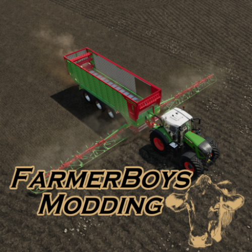
Version 08.12.23.01
1,173 downloads
Magnon Stone Picker BD Update Version 07.12.23.01 Per request by Truzedo I have made some changes to this mod. I usually don’t add huge capacity options, but I have had several requests and have seen many streamers with edited versions. So here you go. Major update I suggest selling your old one before adding this version. It should convert over, but you may lose material or get some initial warnings. There are 4 capacity and unload speed options, each option has to be selected independently in the store. I also added decal color selection and the ability to change material and color on the base and design parts. Materials are steel, chrome, stainless, brushed steel, plastic. Base Cost 132500 Capacity 50K - Free 100K – 2000 500K – 10000 1M – 70000 Discharge options free (when matched up correctly the unit will empty in around 10 seconds) 5K LPS 10K LPS 50K LPS 100K - LPS Update 03.11.23.01 Updated some modDescription to see if it helps with some server issues. Update 26.012.22.01 Lowered ground ref to help issues with pickup. This is the popular Magnon loading wagon with the windrowers converted into a stone picker. $132,500 50k/100k/250k capacity option Rim color, base and secondary/decal color option. Work speed of 15mph Huge thanks to grabbylatoosh and dogface for the testing and suggestions. magnonStoneField.mp4 magnonStoneShop.mp42 points -
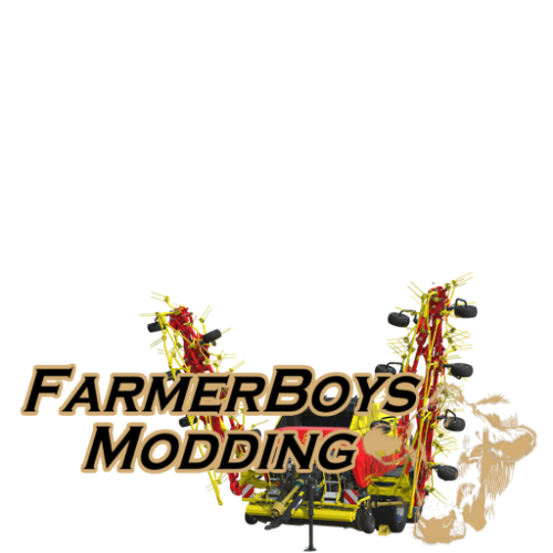
Version 27.12.22.01
592 downloads
Updated version 27.12.22.01 Added the option to add/remove windrowers. Update version 29.01.22.01 Per a request by roar in my discord channel I added a buffer chamber to the baler so that now there is no need to stop you can just keep baling, depending on how much grass is on the ground it may slow down to match the timing of the chamber. This is the in game Impress 185 round baler wrapper with the added windrower arms and silage additive. Silage additive only works with grass it adds 5% yield. The speed is cranked up a bit, for a hired worker to work the best I suggest setting your cruise to around 13MPH if not the worker will not stop quick enough and leave product. Huge thanks to Grabby again for testing along the way. Also I would like to be sure to thank HungryCow Design for making the second windrow array image for me, without it I would not have been able to get effects to work on both sides. Another side note. This isn't my original idea. I found a wagon from FS15 that I believe dates back pre FS13 called the drake wagon. This loading wagon is based off that beast. 2022-12-27 10-08-08.mp42 points -
I had no problems with laying crves before, all I am saying is that creating a spline layout just got more confusing, before it was just a case of selecting either end point ('S' or 'E') selecting Insert and Ctrl B to place the cv on the terrain at the point of your cursor, simple, now you have to be careful which end you start with otherwise you end up going backwards. One sorely needed function in the editor is to allow export of the spline as a nurbs curve (for use in 3d modelling software), something that has been asked for many times over the years along with updated instructions and tutorials.2 points
-
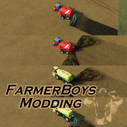
Version 13.03.23.01
121 downloads
Update 13.03.23.01 Slowed application rate (will still fertilize the same just uses less product) and upped capacity to 250K Update 11.03.23.01 Added a selectable option to either be able to use the tank as a spreader or haul all liquids on the map you are playing. Youtube Walkthrough video Update 23.12.22.01 Fixed loading issue with the ats and sped up loading/unloading for both units. Thanks for letting me know @spuds. I converted the drivable slurry trike and ats into units that could simply spread, you can still attach the cultivator implements however now you can simply spread the slurry 30 meters wide without a cultivator. 1 (06).mp4 1 (03).mp42 points -
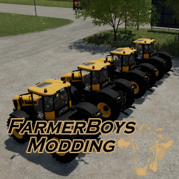
Version 07.11.22.01
201 downloads
The nimble fastrac with hp selection of 250, 550, 750, 999 Bumped speed up a bit Color selectable2 points -
Version 23.11.21.01
203 downloads
FS22 Smarag 9 cultivator converted to a plow and sped up.2 points -
Version 31.05.20.00
608 downloads
This is the draper edited to attach to the Big X, it will work for grass, grain, and corn (processes material to chaff, grass will still be grass). Cost: 45,000 Selectable decals: New Holland, Case, Massey, JD, Krone Work Speed: 22mph, 35kph2 points -
What a GREAT mod. I just love it. And Thank You for all the work you have put into it.2 points
-
Thanks for the testing and the feedback. Awesome to hear positive comments. It was as fun to work on as it is to use.2 points
-
Version 13.03.20.00
1,247 downloads
The New Holland CR1090 BD edited. The pipe will unload even in the back position. This comes in handy if you want to unload in to a sell point or at a silo. I also added tracks to the back, or you have the option to have all wheels or duals. Cost: 43,000 HP: 2000 Speed: 60mph Capacity: 100.000 Color Selectable Rim Color Selectable2 points -
Version 06.10.19.00
295 downloads
Just simply the 2 Nova Cat in game mowers a bit less weight, sped up, and color choice. Work Speed: 21mph CatX8S: $8,000 Cat301S: $5,0002 points -
HI I can't seem to unload pig food at the pigs? Great map btw 🙂 Thanks2 points
-
Awesome work, been looking for something like this since 17 had something similar that I loved to use2 points
-
Version 29.12.18
973 downloads
Version 29.12.18 In game Horsch Cruiser 12XL Cultivator converted in to a plow. Hp just a bit more realistic. To get full speed 300 HP needed. If you don’t like it just search “maxForce” on the xml and lower the number Now colorable Changed hub color Now rims colorable2 points


